- COURSES
- SPECIALS
- BLOG
- MEMBERS
- SHOP
- ABOUT
- ENROLL HERE
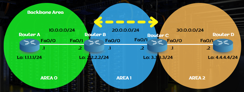
Table of Contents
OSPF Backbone area is Area 0. Normally all the areas are connected to Area 0, the backbone OSPF area. But sometimes, some of the areas can not connect area 0 directly. At these times, we use OSPF Virtual Links to connects these areas to the OSPF backbone area, Area 0. In this lesson, we will learn Cisco OSPF Virtual Link Configuration with Cisco Packet Tracer. We will configure an OSPF Virtual Link, on Cisco Packet Tracer.
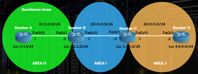
For our Cisco OSPF Virtual-Link Configuration, we will use the below OSPF topology which is consist of one backbone (Area 0) and two other OSPF areas (Area 1 and Area 2).
To do this OSPF Virtual-Link configuration, we will follow the below steps one by one:
Here, we will configure OSPF Virtual-Link, between Router B and Router C. We will use Loopback interface addresses for virtual link configuration.
You can also download all Cisco Packet Tracer Labs on IPCisco.com!
For our OSPF Virtual Link Configuration example, firstly, we need to configure the ip addressing on the physical interfaces and on loopback interfaces. We will configure these ip addresses as expressed above on each router.
Router A(config)# interface Loopback0
Router A(config-if)# ip address 1.1.1.1 255.255.255.0
Router A(config-if)# interface Fa0/0
Router A(config-if)# ip address 10.0.0.1 255.255.255.0
Router A(config-if)# exit
Router B(config)# interface Loopback0
Router B(config-if)# ip address 2.2.2.2 255.255.255.0
Router B(config-if)# interface Fa0/1
Router B(config-if)# ip address 10.0.0.2 255.255.255.0
Router B(config-if)# interface Fa0/0
Router B(config-if)# ip address 20.0.0.1 255.255.255.0
Router B(config-if)# exit
Router C(config)# interface Loopback0
Router C(config-if)# ip address 3.3.3.3 255.255.255.0
Router C(config-if)# interface Fa0/1
Router C(config-if)# ip address 20.0.0.2 255.255.255.0
Router C(config-if)# interface Fa0/0
Router C(config-if)# ip address 30.0.0.1 255.255.255.0
Router C(config-if)# exit
Router D(config)# interface Loopback0
Router D(config-if)# ip address 4.4.4.4 255.255.255.0
Router D(config-if)# interface Fa0/1
Router D(config-if)# ip address 30.0.0.2 255.255.255.0
Router d(config-if)# exit
After interface ip configuration, we will configure OSPF process and add OSPF Networks under this interface. Here, we will use OSPF process number 1. Router A is in Area 0, Router B is Area Border Router (ABR) and it is on both ara 0 and area 1. Again, Router C is an Area Border Router (ABR) and in two different areas, in Area 1 and area 2. And lastly, Router D will be in area 2 only. The interfaces will be added to these ospf process with these areas with network addresses and required wildcard mask.
Router A(config)# router ospf 1
Router A(config-router)# network 10.0.0.0 0.0.0.255 area 0
Router B(config)# router ospf 1
Router B(config-router)# network 10.0.0.0 0.0.0.255 area 0
Router B(config-router)# network 20.0.0.0 0.0.0.255 area 1
Router C(config)# router ospf 1
Router C(config-router)# network 20.0.0.0 0.0.0.255 area 1
Router C(config-router)# network 30.0.0.0 0.0.0.255 area 2
Router D(config)# router ospf 1
Router D(config-router)# network 30.0.0.0 0.0.0.255 area 2
After configuring ip addresses and OSPF processes with networks, now it is time to do the exact OSPF Virtual Link Configuration on Packet Tracer. Here, we will connect Area 2 to Area 0 over Area 1. So, we will create a virtual link between Router B and Router C. On router B, we will set the destination virtual link address as the loopback ip address of router C (3.3.3.3). And on router C, we will set the destination virtual link address as the loopback ip address of Router B (2.2.2.2).
Router B(config)# router ospf 1
Router B(config-router)# area 1 virtual-link 3.3.3.3
Router C(config)# router ospf 1
Router C(config-router)# area 1 virtual-link 2.2.2.2
At the last step, we will check our configuration with the help of “show ip ospf virtual-links” and “show ip ospf neighbor” commands. The output of this command will show us the created virtual link between two devices.
With “show ip ospf virtual-links” command, we can check the virtual link status, associated interface and more.
Router B# show ip ospf virtual-links
Virtual Link OSPF_VL0 to router 3.3.3.3 is up
Run as demand circuit
Transit area 1, via interface FastEthernet0/0, Cost of using 1
Transmit Delay is 1 sec, State POINT_TO_POINT,
Timer intervals configured, Hello 10, Dead 40, Wait 40, Retransmit 5
Hello due in 00:00:06
Adjacency State FULL
Index 1/2, retransmission queue length 0, number of retransmission 0
First 0x0(0)/0x0(0) Next 0x0(0)/0x0(0)
Last retransmission scan length is 0, maximum is 0
Last retransmission scan time is 0 msec, maximum is 0 msec
Router C# show ip ospf virtual-links
Virtual Link OSPF_VL0 to router 2.2.2.2 is up
Run as demand circuit
Transit area 1, via interface FastEthernet1/0, Cost of using 1
Transmit Delay is 1 sec, State POINT_TO_POINT,
Timer intervals configured, Hello 10, Dead 40, Wait 40, Retransmit 5
Hello due in 00:00:07
Adjacency State FULL
Index 1/2, retransmission queue length 0, number of retransmission 0
First 0x0(0)/0x0(0) Next 0x0(0)/0x0(0)
Last retransmission scan length is 0, maximum is 0
Last retransmission scan time is 0 msec, maximum is 0 msec
With “show ip ospf neighbor” command, we can see the loopback interface used with virtual link as ospf neighbor.
Router B# show ip ospf neighbor
Neighbor ID Pri State Dead Time Address Interface
3.3.3.3 0 FULL/ – 00:00:36 20.0.0.2 OSPF_VL0
10.0.0.1 1 FULL/DR 00:00:38 10.0.0.1 FastEthernet1/0
3.3.3.3 1 FULL/DR 00:00:31 20.0.0.2 FastEthernet0/0
Router C# show ip ospf neighbor
Neighbor ID Pri State Dead Time Address Interface
2.2.2.2 1 FULL/BDR 00:00:34 20.0.0.1 FastEthernet1/0
30.0.0.2 1 FULL/DR 00:00:39 30.0.0.2 FastEthernet0/0
2.2.2.2 0 FULL/ – 00:00:31 20.0.0.1 OSPF_VL0
As you can see above, our Cisco Virtual-Link Configuration with Cisco Packet Tracer is successful. Now, Area 2 is connected to Area 0 over Area 1. In OSPF networks, Virtual-Link Configurations are generally used as a temporary solution.


Leave a Reply