In this article series we will concentrate on OSPF Area Types and their configuration examples on Packet Tracer.
You can DOWNLOAD the Packet Tracer example with .pkt format HERE.
As you know from the previous posts, OSPF has 6 different areas. These areas are:
– Backbone Area
– Standard (Normal) Area
– Stub Area
– Totally-Stub Area
– Not-So-Stubby Area (NSSA)
– Totally Not-So-Stubby Area
In this first post, we will focus on Backbone Area and Standard (Normal) Area. Beside this, we will see the configuration of virtual-link on OSPF. What was the virtual-link? It was the link that used to connect the normal areas to the backbone area, if they are not connected directly to the backbone area. Remember, in OSPF, there was a rule. All areas must be connected to the backbone area, Area 0. If they are not, they can temporarily connect to the backbone via virtual-links.

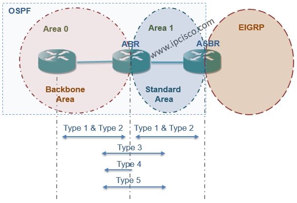
Backbone Area is also a Normal Area but it is Area 0.
Normal Areas accept the Summary LSAs from other Areas (Type 3 and Type 4 LSAs). They accept also the External LSAs (Type 5 LSAs). Type 1 and Type 2 LSA are already accepted inside area.
We talked about theorical too much. This post aims to show you the configuration of this areas and as you know, doing the configuration is the most effective way of learning network protocols.
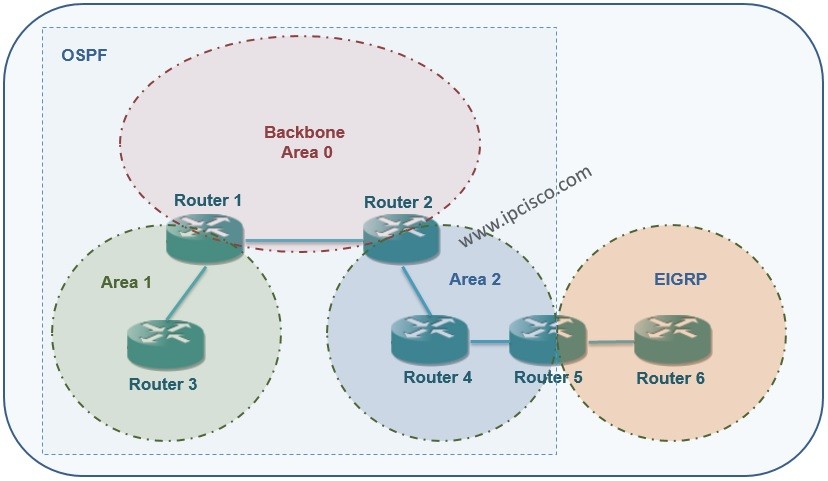
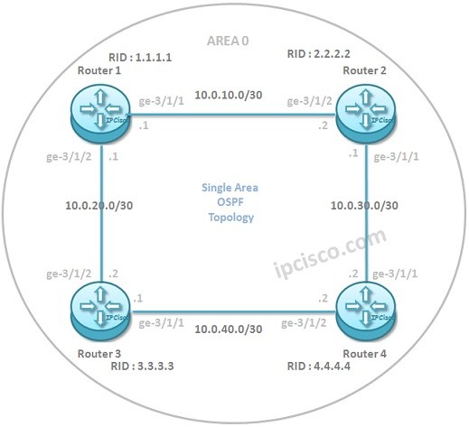
Our topology will be like below fort he first example.

Virtual-Link Example Topology
As you can see, in this topology, there are Backbone Area (Area 0) and three standard (normal) areas (Area 1, Area 2, Area3).
Firstly let’s configure the IP Addresses on all routers:
Router1
Router2
Router3
Router4
Router5
Router6
After this basic interface configurations, let’s configure the OSPF on all routers. Here, OSPF process number will be 1 and the Routerx’s router ID will be x.x.x.x. Beside this, all the connected areas will be configured.
Router1
Router2
Router3
Router4
Router5
Router6
After doing this configuration we will see all the network on Topology Table except Area 3. Area 3 is not directly connected to the Backbone Area,Area 0. So in the routing table of the routers there will be no route to this Area 3.

Other OSPF Area Types on Packet Tracer Lessons
OSPF Area Types on Packet Tracer – Part 1 (Standard Area, Backbone Area, Virtual-Link)
OSPF Area Types on Packet Tracer – Part 2 (OSPF External Routes)
OSPF Area Types on Packet Tracer – Part 3 (Stub Area, Totally-Stub Area, NSSA, Totally NSSA)
You can check the other Packet Tracer Examples below:
Common Cisco Router Configuration Example on Packet Tracer
Router DHCP Configuration Example on Packet Tracer
VTP Configuration Example on Packet Tracer
VLAN Configuration Example on Packet Tracer
STP Configuration Example on Packet Tracer
BGP Configuration Example on Packet Tracer
Port Security Configuration Example on Packet Tracer
RIP Configuration Example on Packet Tracer
CDP Configuration Example on Packet Tracer
OSPF Area Types Example on Packet Tracer (Standard and Backbone Areas)
OSPF External Routes Example on Packet Tracer
OSPF Area Types Example on Packet Tracer (Stub, NSSA, Totally Stubby, Totally NSSA Areas)

Table of Contents
gokhankosem
Gokhan Kosem is a Network Engineer, Instructor and the Founder of IPCisco.com with 15+ years of experience in Cisco, Nokia, Huawei, Juniper, Linux, Service Provider Networks, Routing and Switching technologies.
He has worked on the backbone networks of major service providers and network vendors including Nortel, Alcatel-Lucent (Nokia) and has extensive hands-on experience with Cisco, Huawei, Juniper and Nokia networking technologies.
He has trained thousands of networking students worldwide through IPCisco.com, Udemy, books, labs, quizzes, and educational content across multiple social media platforms.
IPCisco.com | Best Route to Your Dreams


Leave a Reply