Table of Contents
Packet Tracer STP Portfast Configuration
In STP (Spanning Tree Protocol) there are different states. These STP states are: Blocking State, Listenning State, Learning State and Forwarding State. With STP Portfast, Listenning State and Learning State are bypassed. With this configuration, ports rapidly goes to Forwarding State.
The access ports of the switches that connect to hosts can configured with Spanning Tree Portfast. And with Portfast, the host ports rapidly goes to Forwarding State. Here, host means, PCs, Laptops, IP Phone and other user equipments.
You can DOWNLOAD the Cisco Packet Tracer example with .pkt format At the End of This Lesson.
For all Packet Tracer Examples and Files, you can check Packet Tracer Labs Page.
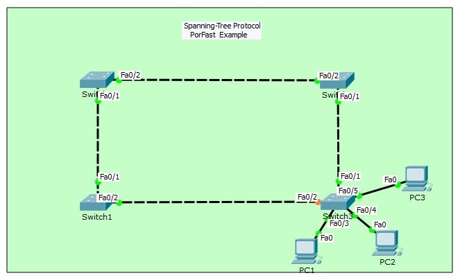
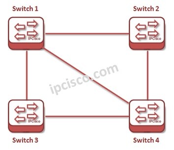
For our Spanning Tree Portfast configuration, we will use the below topology on Packet Tracer. Here, we have four Cisco swithces in our Spanning Tree domain.

You can delete the link of PC2 and then reconnect it for checking the behaviour of STP without Portfast. After this process, you will see STP states one by one.
Switch# show spanning-tree
VLAN0001
Spanning tree enabled protocol ieee
Root ID Priority 32769
Address 0006.2A11.24CC
Cost 38
Port 1(FastEthernet0/1)
Hello Time 2 sec Max Age 20 sec Forward Delay 15 secBridge ID Priority 32769 (priority 32768 sys-id-ext 1)
Address 000A.4139.1675
Hello Time 2 sec Max Age 20 sec Forward Delay 15 sec
Aging Time 20Interface Role Sts Cost Prio.Nbr Type
—————- —- — ——— ——– ——————————–
Fa0/1 Root FWD 19 128.1 P2p
Fa0/2 Altn BLK 19 128.2 P2p
Fa0/3 Desg FWD 19 128.3 P2p
Fa0/4 Desg LSN 19 128.4 P2p
Fa0/5 Desg FWD 19 128.5 P2p
Switch# show spanning-tree
VLAN0001
Spanning tree enabled protocol ieee
Root ID Priority 32769
Address 0006.2A11.24CC
Cost 38
Port 1(FastEthernet0/1)
Hello Time 2 sec Max Age 20 sec Forward Delay 15 secBridge ID Priority 32769 (priority 32768 sys-id-ext 1)
Address 000A.4139.1675
Hello Time 2 sec Max Age 20 sec Forward Delay 15 sec
Aging Time 20Interface Role Sts Cost Prio.Nbr Type
—————- —- — ——— ——– ——————————–
Fa0/1 Root FWD 19 128.1 P2p
Fa0/2 Altn BLK 19 128.2 P2p
Fa0/3 Desg FWD 19 128.3 P2p
Fa0/4 Desg LRN 19 128.4 P2p
Fa0/5 Desg FWD 19 128.5 P2p
Switch# show spanning-tree
VLAN0001
Spanning tree enabled protocol ieee
Root ID Priority 32769
Address 0006.2A11.24CC
Cost 38
Port 1(FastEthernet0/1)
Hello Time 2 sec Max Age 20 sec Forward Delay 15 secBridge ID Priority 32769 (priority 32768 sys-id-ext 1)
Address 000A.4139.1675
Hello Time 2 sec Max Age 20 sec Forward Delay 15 sec
Aging Time 20Interface Role Sts Cost Prio.Nbr Type
—————- —- — ——— ——– ——————————–
Fa0/1 Root FWD 19 128.1 P2p
Fa0/2 Altn BLK 19 128.2 P2p
Fa0/3 Desg FWD 19 128.3 P2p
Fa0/4 Desg FWD 19 128.4 P2p
Fa0/5 Desg FWD 19 128.5 P2p
For all Packet Tracer Examples and Files, you can check Packet Tracer Labs Page.
Now, let’s configure Portfast on all access interfaces. For this, we will use “spanning-tree portfast default” command. This command enables STP Portfast, on all access interfaces.
Switch (config)# spanning-tree portfast default
After Portfast configuration on switch, let’s check the states again by deleting and reconnecting the cable of port Fa0/4. When we delete the cable that on fa0/4 on Packet Tracer, the port is also removed on “show spanning-tree”.
Switch# show spanning-tree
VLAN0001
Spanning tree enabled protocol ieee
Root ID Priority 32769
Address 0006.2A11.24CC
Cost 38
Port 1(FastEthernet0/1)
Hello Time 2 sec Max Age 20 sec Forward Delay 15 secBridge ID Priority 32769 (priority 32768 sys-id-ext 1)
Address 000A.4139.1675
Hello Time 2 sec Max Age 20 sec Forward Delay 15 sec
Aging Time 20Interface Role Sts Cost Prio.Nbr Type
—————- —- — ——— ——– ——————————–
Fa0/1 Root FWD 19 128.1 P2p
Fa0/2 Altn BLK 19 128.2 P2p
Fa0/3 Desg FWD 19 128.3 P2p
Fa0/5 Desg FWD 19 128.5 P2pWhen we connect the cable again, then the port immediatelly become up and go to the Forwarding State.
Switch#
%LINK-5-CHANGED: Interface FastEthernet0/4, changed state to up%LINEPROTO-5-UPDOWN: Line protocol on Interface FastEthernet0/4, changed state to up
Switch# show spanning-tree
VLAN0001
Spanning tree enabled protocol ieee
Root ID Priority 32769
Address 0006.2A11.24CC
Cost 38
Port 1(FastEthernet0/1)
Hello Time 2 sec Max Age 20 sec Forward Delay 15 secBridge ID Priority 32769 (priority 32768 sys-id-ext 1)
Address 000A.4139.1675
Hello Time 2 sec Max Age 20 sec Forward Delay 15 sec
Aging Time 20Interface Role Sts Cost Prio.Nbr Type
—————- —- — ——— ——– ——————————–
Fa0/1 Root FWD 19 128.1 P2p
Fa0/2 Altn BLK 19 128.2 P2p
Fa0/3 Desg FWD 19 128.3 P2p
Fa0/4 Desg FWD 19 128.4 P2pFa0/5 Desg FWD 19 128.5 P2p
As you can see above output, switch ports goes to the Forwarding state immediately after out configuration.
You can DOWNLOAD the Packet Tracer example with .pkt format HERE.

You can check the other Cisco Packet Tracer Examples below:
Common Cisco Router Configuration Example on Packet Tracer
Router DHCP Configuration Example on Packet Tracer
VTP Configuration Example on Packet Tracer
VLAN Configuration Example on Packet Tracer
STP Configuration Example on Packet Tracer
RSTP Configuration with Packet Tracer
STP Portfast Configuration with Packet Tracer
Inter VLAN Routing Configuration on Packet Tracer
Switch Virtual Interface (SVI) Configuration with Packet Tracer
BGP Configuration Example on Packet Tracer
Port Security Configuration Example on Packet Tracer
RIP Configuration Example on Packet Tracer
CDP Configuration Example on Packet Tracer
OSPF Area Types Example on Packet Tracer (Standard and Backbone Areas)
OSPF External Routes Example on Packet Tracer
OSPF Area Types Example on Packet Tracer (Stub, NSSA, Totally Stubby, Totally NSSA Areas)
Standard Access-List Example on Packet Tracer
Extended Access-List Example on Packet Tracer

Gokhan Kosem is a Network Engineer, Instructor and the Founder of IPCisco.com with 15+ years of experience in Cisco, Nokia, Huawei, Juniper, Linux, Service Provider Networks, Routing and Switching technologies.
He has worked on the backbone networks of major service providers and network vendors including Nortel, Alcatel-Lucent (Nokia) and has extensive hands-on experience with Cisco, Huawei, Juniper and Nokia networking technologies.
He has trained thousands of networking students worldwide through IPCisco.com, Udemy, books, labs, quizzes, and educational content across multiple social media platforms.
IPCisco.com | Best Route to Your Dreams


Leave a Reply