

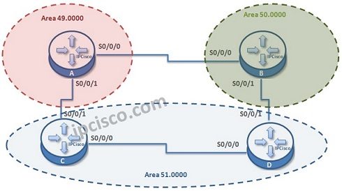
In this Cisco ISIS configuration example, we will configure an ISIS domain and see how to establish ISIS Routing.
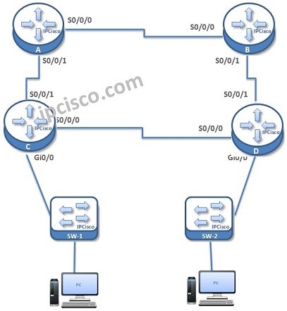
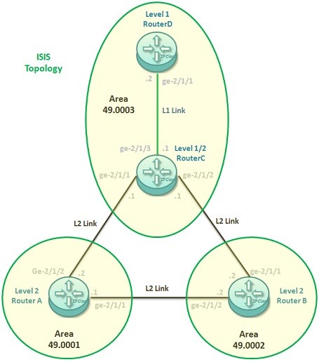
For our example we will use the below four-routered topology. Here, we will have 3 different area. We are using multi area model to show you the link level configurations.
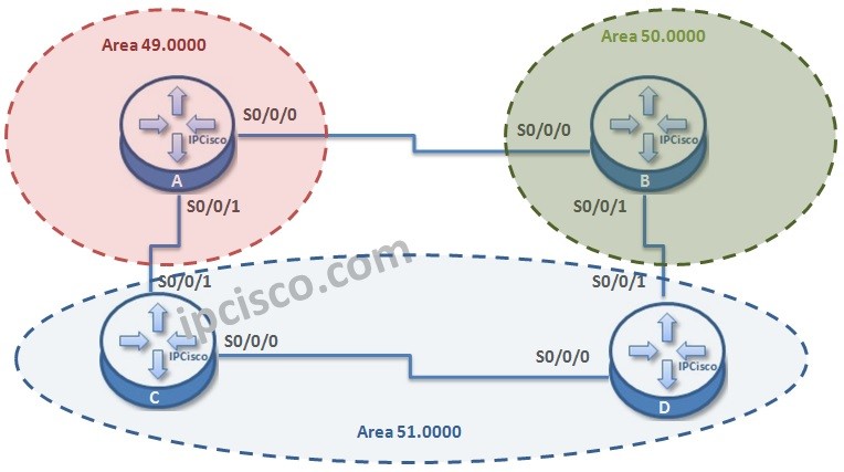
Let’s start the ISIS configuration.
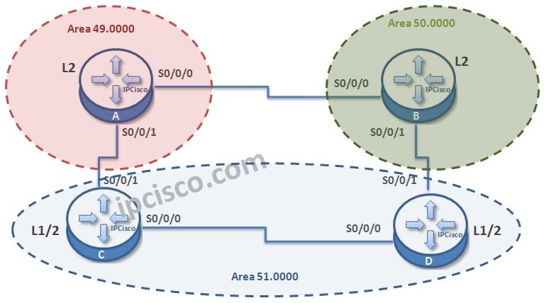
Firstly we will create the router ISIS process with the value “1” and we will give a “net” address to each router. After that we will set the router type. By default all routers are Level 1/2 .
By the way, let’s remember ISIS router types quickly;
• L1 routers, establish neighbourship with only the routers in the same area.
• L2 routers, establish neighbourship with routers in different areas or in the same area.
• L1/2 routers, establish neighbourship with routers in any area.
How about LSDBs?
• L1 routers have Level-1 LSDB for the area
• L2 router s have Level-2 LSD for inter-area (between areas)
• L1 routers has two separate LSDB for both Level-1 and Level-2

The other articles on IS-IS Protocol are below:
Routing With IS-IS Protocol – Part 1
Routing With IS-IS Protocol – Part 2 (IS-IS Addresses)
Routing With IS-IS Protocol – Part 3 (IS-IS Packet Types)
Routing With IS-IS Protocol – Part 4 (IS-IS Adjacency)
Routing With IS-IS Protocol – Part 5 (IS-IS versus OSPF)

Gokhan Kosem is a Network Engineer, Instructor and the Founder of IPCisco.com with 15+ years of experience in Cisco, Nokia, Huawei, Juniper, Linux, Service Provider Networks, Routing and Switching technologies.
He has worked on the backbone networks of major service providers and network vendors including Nortel, Alcatel-Lucent (Nokia) and has extensive hands-on experience with Cisco, Huawei, Juniper and Nokia networking technologies.
He has trained thousands of networking students worldwide through IPCisco.com, Udemy, books, labs, quizzes, and educational content across multiple social media platforms.
IPCisco.com | Best Route to Your Dreams




Leave a Reply