Table of Contents
Packet Tracer GRE Tunnel Configuration
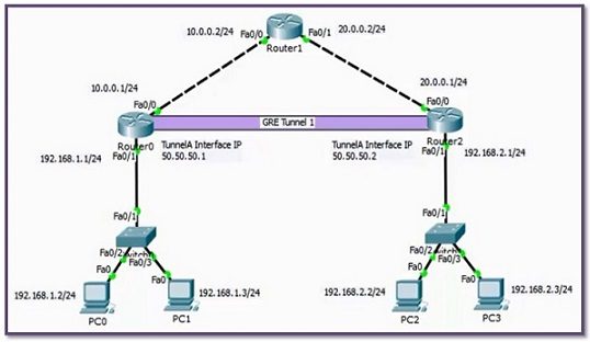
In this confgiuration example, we will see how to configure Cisco GRE (Generic Routing Encapsulation) Tunnel with Packet Tracer. For our GRE Tunnel Configuration example, we will use the below topology and the given IP addresses.
You can DOWNLOAD the Cisco Packet Tracer example with .pkt format At the End of This Lesson.
You can also DOWNLOAD all the Packet Tracer examples with .pkt format in Packet Tracer Labs section.
Here, we assume that all the IP Configurations have been done and we will focus only GRE Tunel Configuration with Packet Tracer.
Let’s start with Router 0.
GRE Tunnel Configuration
In Router 0, we will create the Tunnel interface and then give this interface an IP Address. After that, we we will define the Tunnel Source, with IP Address or with Interface name. Here, we used Interface name. Lastly, we define the Tunnel Destination IP address.
R0(config)# interface Tunnel 1
Now, let’s configure Router 2. We will do the same configuration on Router 2, only IP addresses will change.
GRE Tunnel Static Route
After Tunnel configuration, we need to write a Static Route on Router 0 and Router 2. Because, the routers needs to know how to reach to the users connected to the other end router. In other words, because of the fact that the other end LAN is not directly connected to the router, it needs routing information and we provide this with a Static Route.


Gokhan Kosem is a Network Engineer, Instructor and the Founder of IPCisco.com with 15+ years of experience in Cisco, Nokia, Huawei, Juniper, Linux, Service Provider Networks, Routing and Switching technologies.
He has worked on the backbone networks of major service providers and network vendors including Nortel, Alcatel-Lucent (Nokia) and has extensive hands-on experience with Cisco, Huawei, Juniper and Nokia networking technologies.
He has trained thousands of networking students worldwide through IPCisco.com, Udemy, books, labs, quizzes, and educational content across multiple social media platforms.
IPCisco.com | Best Route to Your Dreams


well documented, scripted and so helpful.
Awesome, packet tracer has really evolved since I first used it back in 2009 for CCNA!