- COURSES
- SPECIALS
- BLOG
- MEMBERS
- SHOP
- BOOKSHELF
- ABOUT
- ENROLL HERE
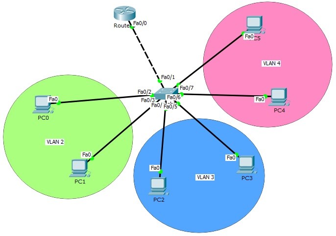
Table of Contents
Inter VLAN Routing allows communication between different VLANs using a Layer 3 device. In this lab, we will configure Router-on-a-Stick in Cisco Packet Tracer step by step. VLANs are virtual LANs that divide a large network into smaller segments, commonly used by companies to separate departments and improve network management. Each VLAN represents a separate logical network, so there is no communication between VLANs by default. To enable communication between these subnetworks, Inter VLAN Routing is required. This method is implemented using the Router-on-a-Stick topology, which is a very common approach in CCNA and CCNP level exams.
In this lesson, you will learn how Inter VLAN Routing works and how to configure Router-on-a-Stick step by step in Cisco Packet Tracer.
You can DOWNLOAD the Packet Tracer example with .pkt format At the End of This Lesson.
Other Inter VLAN Routing Lessons:
In this article, we will use the below Router on Stick topology and we will configure Inter VLAN Routing on Packet Tracer.

For Router on Stick topology (Inter VLAN Routing) configuration, we will create router virtual interfaces under the router interfaces. Then, we will assign each of this virtual interface to a specific VLAN. We will also create our VLANs and configure the PCs on that VLAN. For Router on Stick topology (Inter VLAN Routing), we will use one switch, one router and six PCs in Packet Tracer. And we will have 3 VLANs.
Let’s start to configure our Router on Stick topology (Inter VLAN Routing).
We will use 10.0.0.0/24, 20.0.0.0/24 and 30.0.0.0/24 blocks for our Packet Tracer Router on Stick topology example. The first block will be for VLAN 2, the second will be for VLAN 3 and the last one will be for VLAN 4.
Firstly, we ll configure the IP addresses of the PCs on Packet Tracer like below.
PC0 : 10.0.0.2 255.255.255.0
GW : 10.0.0.1
PC1 : 10.0.0.3 255.255.255.0
GW : 10.0.0.1
PC2 : 20.0.0.2 255.255.255.0
GW : 20.0.0.1
PC3 : 20.0.0.3 255.255.255.0
GW : 20.0.0.1
PC4 : 30.0.0.2 255.255.255.0
GW : 30.0.0.1
PC5 : 30.0.0.3 255.255.255.0
GW : 30.0.0.1
Here, the gateway addresses of the PCs will be the IP address of router virtual interfaces. Each router virtual interface will have an IP addresses as gateway of one of the VLANs.
Now, let’s configure our VLANs and assign the interfaces to these VLANs. Firstly we will create VLAN 2,3 and 4. Then, we will enter the interface range and configure the interface range as access interface. Lastly, we will assign the interface to a specific VLAN with “switchport access vlan” command.
Switch (config) # vlan 2
Switch (config-vlan) # vlan 3
Switch (config-vlan) # vlan 4
Switch (config-vlan) # exit
Switch (config) # interface range fastEthernet 0/2-3
Switch (config-if-range) # switchport mode access
Switch (config-if-range) # switchport access vlan 2
Switch (config-if-range) # exit
Switch (config) # interface range fastEthernet 0/4-5
Switch (config-if-range) # switchport mode access
Switch (config-if-range) # switchport access vlan 3
Switch (config-if-range) # exit
Switch (config) # interface range fastEthernet 0/6-7
Switch (config-if-range) # switchport mode access
Switch (config-if-range) # switchport access vlan 4
Switch (config-if-range) # exit
Our VLAN configurations are OK on the switch now. Let’s verify the VLANs.
You can also DOWNLOAD all the Packet Tracer examples with .pkt format in Packet Tracer Labs section.
Switch# show vlan

VLAN Name Status Ports
---- -------------------------------- --------- -------------------------------
1 default active Fa0/8, Fa0/9, Fa0/10, Fa0/11
Fa0/12, Fa0/13, Fa0/14, Fa0/15
Fa0/16, Fa0/17, Fa0/18, Fa0/19
Fa0/20, Fa0/21, Fa0/22, Fa0/23
Fa0/24, Gig0/1, Gig0/2
2 VLAN0002 active Fa0/2, Fa0/3
3 VLAN0003 active Fa0/4, Fa0/5
4 VLAN0004 active Fa0/6, Fa0/7
1002 fddi-default act/unsup
1003 token-ring-default act/unsup
1004 fddinet-default act/unsup
1005 trnet-default act/unsup

AN Type SAID MTU Parent RingNo BridgeNo Stp BrdgMode Trans1 Trans2
---- ----- ---------- ----- ------ ------ -------- ---- -------- ------ ------
1 enet 100001 1500 - - - - - 0 0
2 enet 100002 1500 - - - - - 0 0
3 enet 100003 1500 - - - - - 0 0
4 enet 100004 1500 - - - - - 0 0
As you can see, for our Router on Stick topology, Interface Fa0/2 and Fa0/3 are the member of VLAN 2, Interface Fa0/4 and Fa0/5 are the member of VLAN 3, Interface Fa0/6 and Fa0/7 are the member of VLAN 4. Interface Fa0/1 is not on the VLAN table. Because it is our Trunking port.
It is time to configure the switch’s router face interface, interface 0/1. We will connect switch to the router, with this interface. This interface will be a trunk port. In our Router on Stick topology, Trunk interface will pass all our VLANs that we allowed.
Switch (config) # interface fastEthernet 0/1
Switch (config-if) # switchport mode trunk
Switch (config-if) # switchport trunk allowed vlan 2,3,4
Switch (config-if) # exit
Our switch configuration is ok, on Packet Tracer. We can configure the router, Router on Stick now. On Router on Stick, we will configure Fa0/0 interface and the router virtual interfaces under this interface for Inter VLAN Routing.
Router (config) # interface fastEthernet 0/0
Router (config-if) # no shutdown
Router (config-if) # exit
Router (config) # interface fastEthernet 0/0.2
Router (config-if) # encapsulation dot1q 2
Router (config-if) # switchport trunk allowed vlan 2,3,4
Router (config-if) # ip address 10.0.0.1 255.255.255.0
Router (config-if) # no shutdown
Router (config-if) # exit
Router (config) # interface fastEthernet 0/0.3
Router (config-if) # encapsulation dot1q 3
Router (config-if) # switchport trunk allowed vlan 2,3,4
Router (config-if) # ip address 20.0.0.1 255.255.255.0
Router (config-if) # no shutdown
Router (config-if) # exit
Router (config) # interface fastEthernet 0/0.4
Router (config-if) # encapsulation dot1q 4
Router (config-if) # switchport trunk allowed vlan 2,3,4
Router (config-if) # ip address 30.0.0.1 255.255.255.0
Router (config-if) # no shutdown
Router (config-if) # exit
Let’s verify our interface configurations on router, Router on Stick.
Router# show ip interface brief
Interface IP-Address OK? Method Status Protocol

FastEthernet0/0 unassigned YES unset up up

FastEthernet0/0.2 10.0.0.1 YES manual up up

FastEthernet0/0.3 20.0.0.1 YES manual up up

FastEthernet0/0.4 30.0.0.1 YES manual up up

FastEthernet0/1 unassigned YES unset administratively down down

Vlan1 unassigned YES unset administratively down down
Now, it is time to verify our Router on Stick (Inter VLAN Routing) configuration. We can verify Router on Stick configuration, simply by pinging from one PC in a VLAN, to another PC in another VLANs.
Let’s do this on PC0. We will ping firstly, PC3 and then PC5.
PC>ping 20.0.0.3
Pinging 20.0.0.3 with 32 bytes of data:
Reply from 20.0.0.3: bytes=32 time=1ms TTL=127
Reply from 20.0.0.3: bytes=32 time=0ms TTL=127
Reply from 20.0.0.3: bytes=32 time=0ms TTL=127
Reply from 20.0.0.3: bytes=32 time=0ms TTL=127
Ping statistics for 20.0.0.3:
Packets: Sent = 4, Received = 4, Lost = 0 (0% loss),
Approximate round trip times in milli-seconds:
Minimum = 0ms, Maximum = 1ms, Average = 0ms
PC>ping 30.0.0.3
Pinging 30.0.0.3 with 32 bytes of data:
Reply from 30.0.0.3: bytes=32 time=1ms TTL=127
Reply from 30.0.0.3: bytes=32 time=0ms TTL=127
Reply from 30.0.0.3: bytes=32 time=0ms TTL=127
Reply from 30.0.0.3: bytes=32 time=1ms TTL=127
Ping statistics for 30.0.0.3:
Packets: Sent = 4, Received = 4, Lost = 0 (0% loss),
Approximate round trip times in milli-seconds:
Minimum = 0ms, Maximum = 1ms, Average = 0ms
In this Cisco Packet Tracer configuration example, we configured Router on Stick topology. In other words, we saw Inter VLAN configuration. On Packet Tracer, we used one router, one switch and six PCs as hardware. We configured three VLANs and we assigned the interfaces to the VLANs. We also configured router interface 0/0 and create additional router virtual interfaces on this router.
Lastly, we saw that, our PCs in different VLANs can ping each other and Inter VLAN configuration is working properly in our Router on Stick topology. In this lesson we have learned Router on Stick Config on Cisco devices.
You can also DOWNLOAD all the Packet Tracer examples with .pkt format in Packet Tracer Labs
You can Check Full Cisco Hands on Course With Packet Tracer


Leave a Reply