- COURSES
- SPECIALS
- BLOG
- MEMBERS
- SHOP
- BOOKSHELF
- ABOUT
- ENROLL HERE
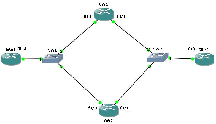
In this section we will do an HSRP Cisco Configuration to understand the issue better. To do this we will use the below HSRP topology. At the end of this article, you will find the GNS3 configuration lab of this lesson.
 example topology, protocols for redundancy")
Before the HSRP (Hot Standby Router Protocol) configuration, we must prepare our topology. We will change the router names and we will assigned the ip addresses of the router interfaces.
For the left side of the topology, we will use 10.10.10.0 network and for the right side, we will use 10.10.20.0 network. All the interfaces connected to the layer 2 switch will be assigned with the ip addresses related to its connected port. For example the fa0/0 interface of the Site1 router will be assigned the ip address 10.10.10.1 and the GW1’s and GW2’s fa0/0 ip addresses will be 10.10.10.2 and 10.10.10.3 orderly.
After interface configuration, we will configure a static route on each Site1 and Site2. In this static route we will use two virtual ip addresses that we will explain in this article. This virtual addresses will be 10.10.10.10 and 10.10.20.20.
Site1(config)# ip route 10.10.20.0 255.255.255.0 10.10.10.10
Site2(config)# ip route 10.10.10.0 255.255.255.0 10.10.20.20
Now our configuration is ready to HSRP configuration. Let’s start on one side(left) on GW1 and GW2 and after that we will configure a second HSRP Cisco Configuration for the other side(right).
GW1
GW1(config)# interface fastethernet 0/0
GW1(config-if)# standby 1 ip 10.10.10.10
GW1(config-if)# standby 1 preempt
GW1(config-if)# standby 1 priority 110
GW1(config-if)# standby 1 track fa0/1
GW1(config-if)# exit
GW1(config)# interface fastethernet 0/1
GW1(config-if)# standby 1 ip 10.10.20.20
GW1(config-if)# standby 1 preempt
GW1(config-if)# exitGW2
GW2
GW2(config)# interface fastethernet 0/0
GW2(config-if)# standby 1 ip 10.10.10.10
GW2(config-if)# standby 1 preempt
GW2(config-if)# standby 1 priority 100
GW2(config-if)# standby 1 track fa0/1
GW2(config-if)# exit
GW2(config)# interface fastethernet 0/1
GW2(config-if)# standby 1 ip 10.10.20.20
GW2(config-if)# standby 1 preempt
GW2(config-if)# exit
You do not need to do this HSRP Cisco Configuration for both sides, but in this configuration, we do it for both sites. After this you can check the configuration with “show standby” command on GW1 and GW2. As you see below, for both redundancy configuration GW1 is the active router and the GW2 is the standby.
 show standby on active router")
 show standby on standby router")


Leave a Reply