- COURSES
- SPECIALS
- BLOG
- MEMBERS
- SHOP
- BOOKSHELF
- ABOUT
- ENROLL HERE
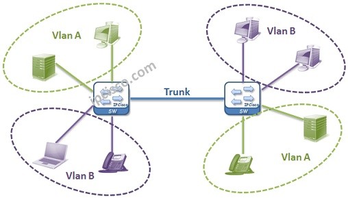
Table of Contents
In this lesson, we will talk about one of the key lessons in networking, especially in switching. We will explain VLAN definition and we will answer the question what is a VLAN? In the following lessons, we will learn the details of Virtual LANs and we will practice with VLAN Configuration Examples . You can also check the definion on Wiki.
If we do a simple VLAN definition, Virtual Local Area Networks are the Logical Virtual Networks that groups network devices in it. In another definition, they are a layer 2 technology with which you can seperate big networks into smaller networks. This can be done for reducing broadcast traffic, network performance improvement, security purpose or to seperate different departments each other and for network flexibility.
")
In a company, different Virtual LANs can be used for different departments. Think about that these departments are IT, HR and Finance. In a single company LAN, with Virtual LANs, each of these department networks become separate networks.
Virtual LANs are Logical networks. In the first place they are defined on the switches and then the ports are assigned to them. By doing this, VLANs members ports appear.
1.Virtual LAN Example
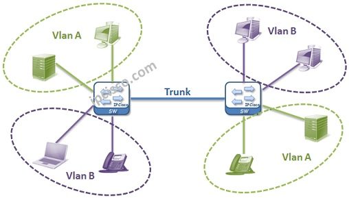
2.Virtual LAN Example
Generally fistly two terms are learned by new engineers about computer networks. These terms are Collision Domain and Broadcast Domain. It can be good to define these terms again. Because in the VLAN lesson, these terms are ciritically important.
Collision domain : A single physical line that a colision can occur. Example: Hubs have one collision domain and only one connected node can make a transfer at any time. Switches collision domain number is like their port number by default.
Broadcast domain : A logical division of networks that all nodes can reach eachother at data link layer(layer 2). Example: Switches are one broadcast domain. Because without any restriction, if one node sends something from one port, all other ports receive it. Routers’ each port is one broadcast domain.
Let’s return our main lesson again. Virtual Local Area Networks help you to build new child broadcast domains in one switch or in one broadcast domain. After Configuring VLANs, each Virtual LAN become a single broadcast domain and without routing, there is no communication between Virtual LANs.
There are also Collision Domains in the Virtual LANs again. Each VLAN has Collision Domain as the number of their assigned ports.
Here, Virtual LANs can be thinked like small switches in the main switch.
On Cisco switches, all the ports are the member of VLAN 1 by default. So if no VLAN Configuration done, all the ports are in the same Virtual LAN, Virtual LAN 1. And they are in the same Broadcast Domain as mentioned above.
By default Native VLAN is 1. By default, all untagged frames are member of it. This Native VLAN can be changed by a trunk port. For example, think about that, one trunk’s NativeVLAN is 5. Here, all the untagged and 5 tagged frames are belong to that Virtual LAN 5. Here the important point is, each end of the connection must be configured with the same configuration.
ISL trunks does not support the NativeVLAN and untagged frames. But dot1.q trunks supports.
On the other hand, Native VLAN is a security risk. To avoid this risk, NativeVLAN can be assigned to an unused port or disabled port. You can also make the trunk ports to tag the Native Virtual LAN.
")
In this lesson, we have talked about Virtual LAN definition, what is a VLAN simply and Native VLAN. Beside, we have remembered Collision and Broadcast Domains. In the next lessons, we will learn more on Virtual LANs and we will learn How to Configure VLANs.
After learning what is a VLAN meaning and some of its details, now, it is time to configure an example for vlanes. For our cisco vlan example, we will use the below topology. Here, we will use three switches which have three PCs connected to them. We will create VLAN 10 and 20.
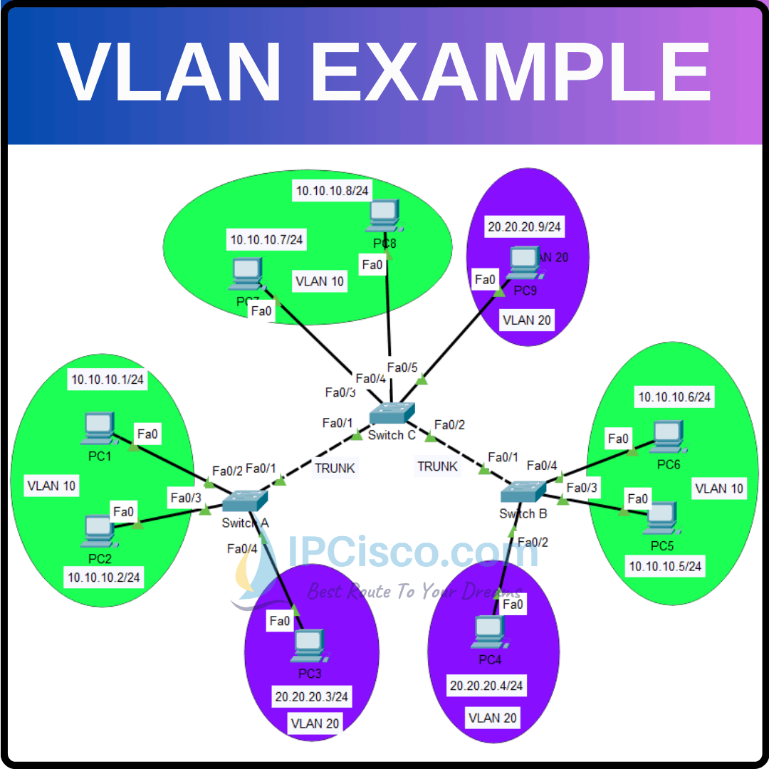
To configure vlanes, we will follow the below steps one by one:
The first configuration step is about ip addressing. We will configure ip addresses of the PCs as it is given on the topology. We will set only ip address and subnet mask.
Here, we will use 10.10.10.0/24 prefix for VLAN 10 and 20.20.20.0/24 for VLAN 20. We will give the below ip addresses to the PCs.
PC1: 10.10.10.1
PC2: 10.10.10.2
PC3 10.10.10.3
PC4: 10.10.10.4
PC5: 10.10.10.5
PC6: 10.10.10.6
PC7: 10.10.10.7
PC8: 10.10.10.8
PC9: 10.10.10.9
We will use 255.255.255.0 subnet mask.
The second thing we will do is creating vlanes. Normally, we do not need to use this step, because during access port vlan assigning, vlanes are automatically created. But here, we are writing these steps to show you how to create them manually.
Switch A# configure terminal
Switch A (config)# vlan 10
Switch A (config-vlan)# vlan 20
Switch B# configure terminal
Switch B (config)# vlan 10
Switch B (config-vlan)# vlan 20
Switch C# configure terminal
Switch C (config)# vlan 10
Switch C (config-vlan)# vlan 20
In the third step, we will set access ports and assign created vlans to these access ports. To do this, we will use the below commands on each switch.
Switch A (config)# interface FastEthernet0/2
Switch A (config-if)# switchport mode access
Switch A (config-if)# switchport access vlan 10
Switch A (config)# interface FastEthernet0/3
Switch A (config-if)# switchport mode access
Switch A (config-if)# switchport access vlan 10
Switch A (config)# interface FastEthernet0/4
Switch A (config-if)# switchport mode access
Switch A (config-if)# switchport access vlan 20
Switch B (config)# interface FastEthernet0/2
Switch B (config-if)# switchport mode access
Switch B (config-if)# switchport access vlan 20
Switch B (config)# interface FastEthernet0/3
Switch B (config-if)# switchport mode access
Switch B (config-if)# switchport access vlan 10
Switch B (config)# interface FastEthernet0/4
Switch B (config-if)# switchport mode access
Switch B (config-if)# switchport access vlan 10
Switch C (config)# interface FastEthernet0/2
Switch c (config-if)# switchport mode access
Switch C (config-if)# switchport access vlan 20
Switch C (config)# interface FastEthernet0/3
Switch c (config-if)# switchport mode access
Switch C (config-if)# switchport access vlan 10
Switch C (config)# interface FastEthernet0/4
Switch c (config-if)# switchport mode access
Switch C (config-if)# switchport access vlan 10
After setting access ports, now it is time to configure trunk ports. To do this, we will use the below commands under trunk interfaces. On Switch C, there are two trunk interfaces, so we will configure two interface as trunks.
Switch A (config)# interface FastEthernet0/1
Switch A (config-if)# switchport mode trunk
Switch A (config-if)# switchport nonegotiate
Switch A (config-if)# switchport trunk allowed vlan 10,20
Switch B (config)# interface FastEthernet0/1
Switch B (config-if)# switchport mode trunk
Switch B (config-if)# switchport nonegotiate
Switch B (config-if)# switchport trunk allowed vlan 10,20
Switch C (config)# interface FastEthernet0/1
Switch C (config-if)# switchport mode trunk
Switch C (config-if)# switchport nonegotiate
Switch C (config-if)# switchport trunk allowed vlan 10,20
Switch C (config-if)# interface FastEthernet0/2
Switch C (config-if)# switchport mode trunk
Switch C (config-if)# switchport nonegotiate
Switch C (config-if)# switchport trunk allowed vlan 10,20
At last step, we will verify our configuration. To do this, we will use “show vlan brief” and “show interface trunk” commands for the verification.
Switch A# show vlan brief

VLAN Name                             Status    Ports
—- ——————————– ——— ——————————-
1    default                          active    Fa0/5, Fa0/6, Fa0/7, Fa0/8
Fa0/9, Fa0/10, Fa0/11, Fa0/12
Fa0/13, Fa0/14, Fa0/15, Fa0/16
Fa0/17, Fa0/18, Fa0/19, Fa0/20
Fa0/21, Fa0/22, Fa0/23, Fa0/24
Gig0/1, Gig0/2
10   VLAN0010                         active    Fa0/2, Fa0/3
20   VLAN0020                         active    Fa0/4
1002 fddi-default                     active
1003 token-ring-default               active
1004 fddinet-default                  active
1005 trnet-default                    active
Switch A# show interfaces trunk
Port        Mode         Encapsulation  Status        Native vlan
Fa0/1       on           802.1q         trunking      1
Port        Vlans allowed on trunk
Fa0/1       10,20
Port        Vlans allowed and active in management domain
Fa0/1       10,20
Port        Vlans in spanning tree forwarding state and not pruned
Fa0/1       10,20
Switch B# show vlan brief

VLAN Name                             Status    Ports
—- ——————————– ——— ——————————-
1    default                          active    Fa0/5, Fa0/6, Fa0/7, Fa0/8
Fa0/9, Fa0/10, Fa0/11, Fa0/12
Fa0/13, Fa0/14, Fa0/15, Fa0/16
Fa0/17, Fa0/18, Fa0/19, Fa0/20
Fa0/21, Fa0/22, Fa0/23, Fa0/24
Gig0/1, Gig0/2
10   VLAN0010                         active    Fa0/3, Fa0/4
20   VLAN0020                         active    Fa0/2
1002 fddi-default                     active
1003 token-ring-default               active
1004 fddinet-default                  active
1005 trnet-default                    active
Switch B# show interfaces trunk
Port        Mode         Encapsulation  Status        Native vlan
Fa0/1       on           802.1q         trunking      1
Port        Vlans allowed on trunk
Fa0/1       10,20
Port        Vlans allowed and active in management domain
Fa0/1       10,20
Port        Vlans in spanning tree forwarding state and not pruned
Fa0/1       10,20
Switch C# show vlan brief
VLAN Name                             Status    Ports
—- ——————————– ——— ——————————-
1    default                          active    Fa0/6, Fa0/7, Fa0/8, Fa0/9
Fa0/10, Fa0/11, Fa0/12, Fa0/13
Fa0/14, Fa0/15, Fa0/16, Fa0/17
Fa0/18, Fa0/19, Fa0/20, Fa0/21
Fa0/22, Fa0/23, Fa0/24, Gig0/1
Gig0/2
10   VLAN0010                         active    Fa0/3, Fa0/4
20   VLAN0020                         active    Fa0/5
1002 fddi-default                     active
1003 token-ring-default               active
1004 fddinet-default                  active
1005 trnet-default                    active
Switch C# show interfaces trunk
Port        Mode         Encapsulation  Status        Native vlan
Fa0/1       on           802.1q         trunking      1
Fa0/2       on           802.1q         trunking      1
Port        Vlans allowed on trunk
Fa0/1       10,20
Fa0/2       10,20
Port        Vlans allowed and active in management domain
Fa0/1       10,20
Fa0/2       10,20
Port        Vlans in spanning tree forwarding state and not pruned
Fa0/1       10,20
Fa0/2       10,20
Beside we will ping PCs in the same VLAN but connected to different VLANs. For example, we will ping from PC1 to PC5 or PC3 to PC4.
Firstly, let’s ping from PC 1 to PC 5 and PC8. These PCs are in VLAN 10.
C:\> ping 10.10.10.5
Pinging 10.10.10.5 with 32 bytes of data:
Reply from 10.10.10.5: bytes=32 time<1ms TTL=128
Reply from 10.10.10.5: bytes=32 time=1ms TTL=128
Reply from 10.10.10.5: bytes=32 time<1ms TTL=128
Reply from 10.10.10.5: bytes=32 time<1ms TTL=128
Ping statistics for 10.10.10.5:
Packets: Sent = 4, Received = 4, Lost = 0 (0% loss),
Approximate round trip times in milli-seconds:
Minimum = 0ms, Maximum = 1ms, Average = 0ms
C:\> ping 10.10.10.8
Pinging 10.10.10.8 with 32 bytes of data:
Reply from 10.10.10.8: bytes=32 time<1ms TTL=128
Reply from 10.10.10.8: bytes=32 time=1ms TTL=128
Reply from 10.10.10.8: bytes=32 time<1ms TTL=128
Reply from 10.10.10.8: bytes=32 time<1ms TTL=128
Ping statistics for 10.10.10.8:
Packets: Sent = 4, Received = 4, Lost = 0 (0% loss),
Approximate round trip times in milli-seconds:
Minimum = 0ms, Maximum = 1ms, Average = 0ms
Then, let’s ping from PC3 to PC4 and PC9. These PCs are in VLAN 20.
C:\> ping 20.20.20.4
Pinging 20.20.20.4 with 32 bytes of data:
Reply from 20.20.20.4: bytes=32 time=1ms TTL=128
Reply from 20.20.20.4: bytes=32 time<1ms TTL=128
Reply from 20.20.20.4: bytes=32 time<1ms TTL=128
Reply from 20.20.20.4: bytes=32 time=1ms TTL=128
Ping statistics for 20.20.20.4:
Packets: Sent = 4, Received = 4, Lost = 0 (0% loss),
Approximate round trip times in milli-seconds:
Minimum = 0ms, Maximum = 1ms, Average = 0ms
C:\> ping 20.20.20.9
Pinging 20.20.20.9 with 32 bytes of data:
Reply from 20.20.20.9: bytes=32 time<1ms TTL=128
Reply from 20.20.20.9: bytes=32 time<1ms TTL=128
Reply from 20.20.20.9: bytes=32 time=2ms TTL=128
Reply from 20.20.20.9: bytes=32 time=1ms TTL=128
Ping statistics for 20.20.20.9:
Packets: Sent = 4, Received = 4, Lost = 0 (0% loss),
Approximate round trip times in milli-seconds:
Minimum = 0ms, Maximum = 2ms, Average = 0ms


Good for learning
Thank you Masanja:) good luck!