- COURSES
- SPECIALS
- BLOG
- MEMBERS
- SHOP
- BOOKSHELF
- ABOUT
- ENROLL HERE
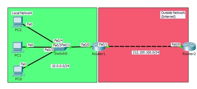
Table of Contents
In previous lessons, we have talked about Static NAT Configuration on Packet Tracer. Here, we will focus on another types of NAT, Dynamic NAT Configuration on Packet Tracer. You will learn How to Configure Dynamic NAT Configuration on Cisco routers. As in Static NAT, in Dynamic NAT, the interfaces must be identified as inside and outside again. Then we will define a Dynamic Address Pool on the NAT router. The ip address will be choosen in this pool to be assigned as source ip address.
We will use Dynamic NAT topology below for our Dynamic NAT Configuration Packet Tracer example. And we will use Cisco Packet Tracer as a network simulation program.
Access Complete Packet Tracer Configuration Course For Cisco Hands on Experience
")
In our Dynamic NAT topology on Packet Tracer, we will have two networks again, one local and one outside network. In local network, we have three PCs and we will provide internet access to these PCs. Our Dynamic NAT configuration topology on Packet Tracer will be a small simulation of real world office Internet access.
Firstly, before Dynamic NAT configuration, we will prepare our network with our IP configurations on PCS and routers. We will provide full connectivity end to end before starting our NAT Config.
Our PCs on Packet Tracer will be configured with below IP addresses.
PC0 : 10.0.0.2 255.255.255.0 GW:10.0.0.1
PC1 : 10.0.0.3 255.255.255.0 GW:10.0.0.1
PC2 : 10.0.0.4 255.255.255.0 GW:10.0.0.1
Router1(config)# interface FastEthernet0/0
Router1(config-if)# ip address 10.0.0.1 255.255.255.0
Router1(config-if)# no shutdown
Router1(config-if)# exit
Router1(config)# interface FastEthernet0/1
Router1(config-if)# ip address 212.100.100.2 255.255.255.0
Router1(config-if)# no shutdown
Router1(config-if)# exit
Router2(config)# interface FastEthernet0/0
Router2(config-if)# ip address 212.100.100.1 255.255.255.0
Router2(config-if)# no shutdown
Router2(config-if)# exit
Router2(config)# ip default-gateway 212.100.100.2
Firstly let’s check the ping packet’s source address when we are pinging from PC 0 to Router2. As you can see below, the source address will be the PC 0 ‘s IP address. To see the packet you must enable NAT debug mode on Router2 by “debug ip nat” command.Check the below screenshots.
PC0> ping 212.100.100.1
Pinging 212.100.100.1 with 32 bytes of data:

Reply from 212.100.100.1: bytes=32 time=13ms TTL=254
Reply from 212.100.100.1: bytes=32 time=1ms TTL=254
Reply from 212.100.100.1: bytes=32 time=1ms TTL=254
Reply from 212.100.100.1: bytes=32 time=2ms TTL=254

Ping statistics for 212.100.100.1:
Packets: Sent = 4, Received = 4, Lost = 0 (0% loss),
Approximate round trip times in milli-seconds:
Minimum = 1ms, Maximum = 13ms, Average = 4ms
Router2# debug ip nat
IP NAT debugging is on
Router2#
ICMP: echo reply sent, src 212.100.100.1, dst 10.0.0.2

ICMP: echo reply sent, src 212.100.100.1, dst 10.0.0.2

ICMP: echo reply sent, src 212.100.100.1, dst 10.0.0.2

ICMP: echo reply sent, src 212.100.100.1, dst 10.0.0.2
Now let’s do the Dynamic NAT configuration on Router1.
Router1(config)# interface FastEthernet0/0
Router1(config-if)# ip nat inside
Router1(config-if)# exit
Router1(config)# interface FastEthernet0/1
Router1(config-if)# ip nat outside
Router1(config-if)# exit
Lastly, with an Access-List (ACL) we will specify the private addresses to be allowed to be dynamically translated. We will creatre an IP Pool with theIP addresses from 50.50.50.1 to 50.50.50.100 . Then we will match this pool with IP block defined with ACL. We will assign this IP Pool towards NAT inside.
Router1(config)# access-list 10 permit 10.10.10.0 0.0.0.255
Router1(config)# ip nat pool IPCISCO 50.50.50.1 50.50.50.100 netmask 255.255.255.0
Router1(config)# ip nat inside source list 10 pool IPCISCO
Here, these allowed addresses above will be tranlated to a value in public address pool that will be dynamically choosen.
After Dynamic NAT configuration Packet Tracer example, it is time to verify Cisco Dynamic NAT Configuration on Packet Tracer with the same ping packet’s source IP address control. Open the debug mode on Router2 with “debug ip nat” command and ping the Router2 from PC0, PC1 and PC2.
PC0>ping 212.100.100.1
Pinging 212.100.100.1 with 32 bytes of data:

Reply from 212.100.100.1: bytes=32 time=0ms TTL=254
Reply from 212.100.100.1: bytes=32 time=1ms TTL=254
Reply from 212.100.100.1: bytes=32 time=1ms TTL=254
Reply from 212.100.100.1: bytes=32 time=1ms TTL=254

Ping statistics for 212.100.100.1:
Packets: Sent = 4, Received = 4, Lost = 0 (0% loss),
Approximate round trip times in milli-seconds:
Minimum = 0ms, Maximum = 1ms, Average = 0ms
Router2# debug ip nat
IP NAT debugging is on
Router2#
ICMP: echo reply sent, src 212.100.100.1, dst 50.50.50.1
ICMP: echo reply sent, src 212.100.100.1, dst 50.50.50.1
ICMP: echo reply sent, src 212.100.100.1, dst 50.50.50.1
ICMP: echo reply sent, src 212.100.100.1, dst 50.50.50.1
Router2#
IP: tableid=0, s=50.50.50.5 (FastEthernet0/0), d=212.100.100.1 (FastEthernet0/0), routed via RIB

IP: s=50.50.50.5 (FastEthernet0/0), d=212.100.100.1 (FastEthernet0/0), len 128, rcvd 3

ICMP: echo reply sent, src 212.100.100.1, dst 50.50.50.5

IP: tableid=0, s=212.100.100.1 (local), d=50.50.50.5 (FastEthernet0/0), routed via RIB

IP: s=212.100.100.1 (local), d=50.50.50.5 (FastEthernet0/0), len 128, sending

...
PC1>ping 212.100.100.1
Pinging 212.100.100.1 with 32 bytes of data:

Reply from 212.100.100.1: bytes=32 time=2ms TTL=254
Reply from 212.100.100.1: bytes=32 time=1ms TTL=254
Reply from 212.100.100.1: bytes=32 time=1ms TTL=254
Reply from 212.100.100.1: bytes=32 time=1ms TTL=254

Ping statistics for 212.100.100.1:
Packets: Sent = 4, Received = 4, Lost = 0 (0% loss),
Approximate round trip times in milli-seconds:
Minimum = 1ms, Maximum = 2ms, Average = 1ms
Router2#
ICMP: echo reply sent, src 212.100.100.1, dst 50.50.50.2
ICMP: echo reply sent, src 212.100.100.1, dst 50.50.50.2
ICMP: echo reply sent, src 212.100.100.1, dst 50.50.50.2
ICMP: echo reply sent, src 212.100.100.1, dst 50.50.50.2

Router2#
IP: tableid=0, s=50.50.50.5 (FastEthernet0/0), d=212.100.100.1 (FastEthernet0/0), routed via RIB

IP: s=50.50.50.5 (FastEthernet0/0), d=212.100.100.1 (FastEthernet0/0), len 128, rcvd 3

ICMP: echo reply sent, src 212.100.100.1, dst 50.50.50.5

IP: tableid=0, s=212.100.100.1 (local), d=50.50.50.5 (FastEthernet0/0), routed via RIB

IP: s=212.100.100.1 (local), d=50.50.50.5 (FastEthernet0/0), len 128, sending

IP: tableid=0, s=50.50.50.5 (FastEthernet0/0), d=212.100.100.1 (FastEthernet0/0), routed via RIB

IP: s=50.50.50.5 (FastEthernet0/0), d=212.100.100.1 (FastEthernet0/0), len 128, rcvd 3

ICMP: echo reply sent, src 212.100.100.1, dst 50.50.50.5

IP: tableid=0, s=212.100.100.1 (local), d=50.50.50.5 (FastEthernet0/0), routed via

...
PC2>ping 212.100.100.1
Pinging 212.100.100.1 with 32 bytes of data:

Reply from 212.100.100.1: bytes=32 time=1ms TTL=254
Reply from 212.100.100.1: bytes=32 time=0ms TTL=254
Reply from 212.100.100.1: bytes=32 time=1ms TTL=254
Reply from 212.100.100.1: bytes=32 time=1ms TTL=254

Ping statistics for 212.100.100.1:
Packets: Sent = 4, Received = 4, Lost = 0 (0% loss),
Approximate round trip times in milli-seconds:
Minimum = 0ms, Maximum = 1ms, Average = 0ms

Router2#
ICMP: echo reply sent, src 212.100.100.1, dst 50.50.50.3
ICMP: echo reply sent, src 212.100.100.1, dst 50.50.50.3
ICMP: echo reply sent, src 212.100.100.1, dst 50.50.50.3
ICMP: echo reply sent, src 212.100.100.1, dst 50.50.50.3
If you would like to learn other NAT Types, you can check the other lessons relatd with Network Address Translation. You can find an example for ech of these NAT types. Beside, there is also a NAT Types article at the beginning of these Lessons.


Leave a Reply