- COURSES
- SPECIALS
- BLOG
- MEMBERS
- SHOP
- BOOKSHELF
- ABOUT
- ENROLL HERE
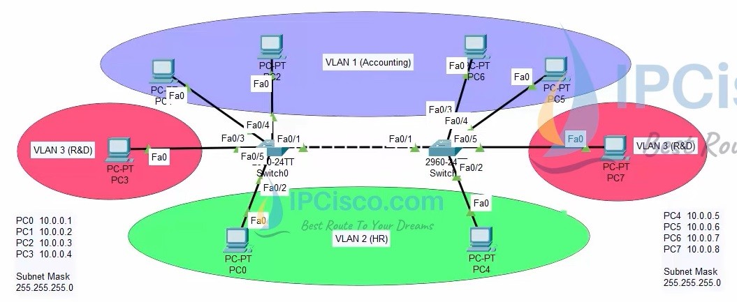
Table of Contents
In this VLAN Cisco Packet Tracer Example, we will learn how to configure VLANs on Cisco switches. For this lesson, we will use the VLAN topology below. In this topology, there are 2 Cisco Catalyst 2960-24 switches and 8 PCs. After this VLAN Packet Tracer Example, you can configure VLANs on your network easily. VLANs are also very important for Cisco CCNA, CCNP and CCIE Certifications.
Packet Tracer VLAN Topology Example
You can DOWNLOAD the Cisco Packet Tracer example with .pkt format at the end of the lesson.
For all Packet Tracer Examples and Files, you can check Packet Tracer Labs Page.
In this Cisco VLAN configuration example, we will follow the below configuration steps one by one:
For our VLAN Configuration example, we will set our PC IPaddresses as below. These ip addresses will be required at the end of this configuration example to test our configuration for Virtual LAN verification.
PC 0 –> 10.0.0.1 VLAN 2 (HR)
PC 1 –> 10.0.0.2 VLAN 1 (Accounting)
PC 2 –> 10.0.0.3 VLAN 1 (Accounting)
PC 3 –> 10.0.0.4 VLAN 3 (R&D)
PC 4 –> 10.0.0.5 VLAN 2 (HR)
PC 5 –> 10.0.0.6 VLAN 1 (Accounting)
PC 6 –> 10.0.0.7 VLAN 1 (Accounting)
PC 7 –> 10.0.0.8 VLAN 3 (R&D)
After PC IP configurations, now, we can start our VLAN Packet Tracer Configuration steps.
To create a VLAN on a Cisco switch, we use “vlan vlan-id” command under global configuration mode. Here, we will create VLAN 2 and VLAN 3. By default VLAN 1 has already created. We will also give a name to these vlans with “name vlan-name” command.
Switch 1# configure terminal
Switch 1(config)# vlan 1
Switch 1(config-vlan)# name Accounting
Switch 1(config-vlan)# vlan 2
Switch 1(config-vlan)# name HR
Switch 1(config-vlan)# vlan 3
Switch 1(config-vlan)# name R&D
We will do the similar configuration on switch 2 also.
Switch 2# configure terminal
Switch 2(config)# vlan 1
Switch 2(config-vlan)# name Accounting
Switch 2(config-vlan)# vlan 2
Switch 2(config-vlan)# name HR
Switch 2(config-vlan)# vlan 3
Switch 2(config-vlan)# name R&D
Access ports are the ports that can be a member of a single VLAN. To configure a port as access port to assign a specific VLAN, we will use two commands. We use “switchport mode access” command to set the interface as access port. Then we use “switchport access vlan vlan-id” command to assign the related VLAN to that interface.
Here, we will configure fastEthernet 0/2 as the member of VLAN 2, fastEthernet 0/3 and fastEthernet 0/4 as the member of VLAN 1 and fastEthernet 0/5 as the member of VLAN 3.
Switch 1(config)# interface fastEthernet 0/2
Switch 1(config-if)# switchport mode access
Switch 1(config-if)# switchport access vlan 2
Switch 1(config-if)#
Switch 1(config-if)# interface fastEthernet 0/3
Switch 1(config-if)# switchport mode access
Switch 1(config-if)# switchport access vlan 1
Switch 1(config-if)#
Switch 1(config-if)# interface fastEthernet 0/4
Switch 1(config-if)# switchport mode access
Switch 1(config-if)# switchport access vlan 1
Switch 1(config-if)#
Switch 1(config)# interface fastEthernet 0/5
Switch 1(config-if)# switchport mode access
Switch 1(config-if)# switchport access vlan 3
We will do the similar configuration on the second switch with some differences. Here, we will configure fastEthernet 0/2 as the member of VLAN 3. while we will configure fastEthernet 0/3 and fastEthernet 0/4 as the member of VLAN 2.
Switch 2(config)# interface fastEthernet 0/2
Switch 2(config-if)# switchport mode access
Switch 2(config-if)# switchport access vlan 2
Switch 2(config-if)#
Switch 2(config-if)# interface fastEthernet 0/3
Switch 2(config-if)# switchport mode access
Switch 2(config-if)# switchport access vlan 1
Switch 2(config-if)#
Switch 2(config-if)# interface fastEthernet 0/4
Switch 2(config-if)# switchport mode access
Switch 2(config-if)# switchport access vlan 1
Switch 2(config-if)#
Switch 2(config-if)# interface fastEthernet 0/5
Switch 2(config-if)# switchport mode access
Switch 2(config-if)# switchport access vlan 3
After creating VLANs, setting access ports and assigning VLANs, now it is time to create Trunk ports that will allow all our VLANs. To set a port as trunk port we will use “switchport mode trunk” command. Then we will use “no negotiate” command to prevent negotiation about the port role. Lastly, we will add the allowed VLANs on this Trunk port with “switchport trunk allowed vlan vlan-range” command.
Here, our trunk ports will be fastEthernet 0/1.
Switch 1(config)# interface fastEthernet 0/1
Switch 1(config-if)# switchport mode trunk
Switch 1(config-if)# switchport nonegotiate
Switch 1(config-if)# switchport trunk allowed vlan 1-3
We will do the same configuration on the second Cisco switch:
Switch 2(config)# interface fastEthernet 0/1
Switch 2(config-if)# switchport mode trunk
Switch 2(config-if)# switchport nonegotiate
Switch 2(config-if)# switchport trunk allowed vlan 1-3
After our configuration steps, we will save our configuration with “copy running-config startup-config” command on both Cisco switches in packet tracer.
Switch 1(config-if)# end
Switch 1# copy running-config startup-config
Switch 2(config-if)# end
Switch 2# copy running-config startup-config
Our last step of VLAN Packet Tracer Example is configuration verification. to verify our VLAN Packet Tracer Configuration, we will use verification commands like “show vlan brief“, “show interfaces“, “show interfaces trunk” etc.
To verify Cisco Packet Tracer VLAN configuration, firstly we will use “show vlan brief” command. With this command, we can see the creatd VLANs and the ports that are assigned to these VLANs. Here, the port that is not appear is Trunk port, fastEthernet 0/1.
Switch1#show vlan brief

VLAN Name Status Ports
---- -------------------------------- --------- -------------------------------
1 default active Fa0/3, Fa0/4, Fa0/6, Fa0/7
Fa0/8, Fa0/9, Fa0/10, Fa0/11
Fa0/12, Fa0/13, Fa0/14, Fa0/15
Fa0/16, Fa0/17, Fa0/18, Fa0/19
Fa0/20, Fa0/21, Fa0/22, Fa0/23
Fa0/24, Gig0/1, Gig0/2
2 HR active Fa0/2
3 R&D active Fa0/5
1002 fddi-default active
1003 token-ring-default active
1004 fddinet-default active
1005 trnet-default active
For all Packet Tracer Examples and Files, you can check Packet Tracer Labs Page.
Another important command on VLAN verification is using “show interfaces interface switchport” command. With this command, we can see a lot of details about our VLAN configuration.
Switch1#show interfaces fastethernet 0/1 switchport

Name: Fa0/1
Switchport: Enabled
Administrative Mode: trunk
Operational Mode: trunk
Administrative Trunking Encapsulation: dot1q
Operational Trunking Encapsulation: dot1q
Negotiation of Trunking: On
Access Mode VLAN: 1 (default)
Trunking Native Mode VLAN: 1 (default)
Voice VLAN: none
Administrative private-vlan host-association: none
Administrative private-vlan mapping: none
Administrative private-vlan trunk native VLAN: none
Administrative private-vlan trunk encapsulation: dot1q
Administrative private-vlan trunk normal VLANs: none
Administrative private-vlan trunk private VLANs: none
Operational private-vlan: none
Trunking VLANs Enabled: 1-3
Pruning VLANs Enabled: 2-1001
Capture Mode Disabled
Capture VLANs Allowed: ALL
Protected: false
Unknown unicast blocked: disabled
Unknown multicast blocked: disabled
Appliance trust: none
Switch1#show interfaces fastethernet 0/2 switchport

Name: Fa0/2
Switchport: Enabled
Administrative Mode: static access
Operational Mode: static access
Administrative Trunking Encapsulation: dot1q
Operational Trunking Encapsulation: native
Negotiation of Trunking: Off
Access Mode VLAN: 2 (HR)
Trunking Native Mode VLAN: 1 (default)
Voice VLAN: none
Administrative private-vlan host-association: none
Administrative private-vlan mapping: none
Administrative private-vlan trunk native VLAN: none
Administrative private-vlan trunk encapsulation: dot1q
Administrative private-vlan trunk normal VLANs: none
Administrative private-vlan trunk private VLANs: none
Operational private-vlan: none
Trunking VLANs Enabled: All
Pruning VLANs Enabled: 2-1001
Capture Mode Disabled
Capture VLANs Allowed: ALL
Protected: false
Unknown unicast blocked: disabled
Unknown multicast blocked: disabled
Appliance trust: none
Switch1#show interfaces fastethernet 0/3 switchport

Name: Fa0/3
Switchport: Enabled
Administrative Mode: static access
Operational Mode: static access
Administrative Trunking Encapsulation: dot1q
Operational Trunking Encapsulation: native
Negotiation of Trunking: Off
Access Mode VLAN: 1 (default)
Trunking Native Mode VLAN: 1 (default)
Voice VLAN: none
Administrative private-vlan host-association: none
Administrative private-vlan mapping: none
Administrative private-vlan trunk native VLAN: none
Administrative private-vlan trunk encapsulation: dot1q
Administrative private-vlan trunk normal VLANs: none
Administrative private-vlan trunk private VLANs: none
Operational private-vlan: none
Trunking VLANs Enabled: All
Pruning VLANs Enabled: 2-1001
Capture Mode Disabled
Capture VLANs Allowed: ALL
Protected: false
Unknown unicast blocked: disabled
Unknown multicast blocked: disabled
Appliance trust: none
Switch1#show interfaces fastethernet 0/4 switchport

Name: Fa0/4
Switchport: Enabled
Administrative Mode: static access
Operational Mode: static access
Administrative Trunking Encapsulation: dot1q
Operational Trunking Encapsulation: native
Negotiation of Trunking: Off
Access Mode VLAN: 1 (default)
Trunking Native Mode VLAN: 1 (default)
Voice VLAN: none
Administrative private-vlan host-association: none
Administrative private-vlan mapping: none
Administrative private-vlan trunk native VLAN: none
Administrative private-vlan trunk encapsulation: dot1q
Administrative private-vlan trunk normal VLANs: none
Administrative private-vlan trunk private VLANs: none
Operational private-vlan: none
Trunking VLANs Enabled: All
Pruning VLANs Enabled: 2-1001
Capture Mode Disabled
Capture VLANs Allowed: ALL
Protected: false
Unknown unicast blocked: disabled
Unknown multicast blocked: disabled
Appliance trust: none
Switch1#show interfaces fastethernet 0/5 switchport

Name: Fa0/5
Switchport: Enabled
Administrative Mode: static access
Operational Mode: static access
Administrative Trunking Encapsulation: dot1q
Operational Trunking Encapsulation: native
Negotiation of Trunking: Off
Access Mode VLAN: 3 (R&D)
Trunking Native Mode VLAN: 1 (default)
Voice VLAN: none
Administrative private-vlan host-association: none
Administrative private-vlan mapping: none
Administrative private-vlan trunk native VLAN: none
Administrative private-vlan trunk encapsulation: dot1q
Administrative private-vlan trunk normal VLANs: none
Administrative private-vlan trunk private VLANs: none
Operational private-vlan: none
Trunking VLANs Enabled: All
Pruning VLANs Enabled: 2-1001
Capture Mode Disabled
Capture VLANs Allowed: ALL
Protected: false
Unknown unicast blocked: disabled
Unknown multicast blocked: disabled
Appliance trust: none
Another important VLAN command is “show interfaces trunk” command. With this command, we can see the details of VLAN Trunk ports.
Switch1#show interfaces trunk
Port      Mode     Encapsulation     Status      Native vlan
Fa0/1      on             802.1q            trunking            1

Port Vlans allowed on trunk
Fa0/1 1-3

Port Vlans allowed and active in management domain
Fa0/1 1,2,3

Port Vlans in spanning tree forwarding state and not pruned
Fa0/1 1,2,3
You can check the same outputs for switch 2. The outputs for both switch 1 and swicth too are also in the below configuration documents.
Switch 2#show vlan brief
Switch 2#show interfaces fastEthernet 0/1 switchport
Switch 2#show interfaces fastEthernet 0/2 switchport
Switch 2#show interfaces fastEthernet 0/3 switchport
Switch 2#show interfaces fastEthernet 0/4 switchport
Switch 2#show interfaces fastEthernet 0/5 switchport
Switch 2#show interfaces trunk
To verify the communication between same VLANs now we will use ping command to check the communication between two PCs in the same VLAN. Here, if the PCs are in the same VLAN, the ping will successful. If they are in different VLANs, ping will not be successful.
PC1:\>ipconfig

FastEthernet0 Connection:(default port)
Connection-specific DNS Suffix..:
Link-local IPv6 Address.........: FE80::201:C7FF:FE36:68DA
IPv6 Address....................: ::
IPv4 Address....................: 10.0.0.2
Subnet Mask.....................: 255.255.255.0
Default Gateway.................: :: 0.0.0.0
PC1:\>ping 10.0.0.6

Pinging 10.0.0.6 with 32 bytes of data:
Reply from 10.0.0.6: bytes=32 time<1ms TTL=128
Reply from 10.0.0.6: bytes=32 time<1ms TTL=128
Reply from 10.0.0.6: bytes=32 time<1ms TTL=128
Reply from 10.0.0.6: bytes=32 time<1ms TTL=128

Ping statistics for 10.0.0.6:
Packets: Sent = 4, Received = 4, Lost = 0 (0% loss),
Approximate round trip times in milli-seconds:
Minimum = 0ms, Maximum = 0ms, Average = 0ms
PC1:\>ping 10.0.0.7

Pinging 10.0.0.7 with 32 bytes of data:
Reply from 10.0.0.7: bytes=32 time<1ms TTL=128
Reply from 10.0.0.7: bytes=32 time<1ms TTL=128
Reply from 10.0.0.7: bytes=32 time<1ms TTL=128
Reply from 10.0.0.7: bytes=32 time<1ms TTL=128

Ping statistics for 10.0.0.7:
Packets: Sent = 4, Received = 4, Lost = 0 (0% loss),
Approximate round trip times in milli-seconds:
Minimum = 0ms, Maximum = 0ms, Average = 0ms
Now, let’s ping from PC3 tom PC7. They are both in VLAN 3 but in different switches.
PC3:\>ping 10.0.0.8

Pinging 10.0.0.8 with 32 bytes of data:

Reply from 10.0.0.8: bytes=32 time<1ms TTL=128
Reply from 10.0.0.8: bytes=32 time<1ms TTL=128
Reply from 10.0.0.8: bytes=32 time=1ms TTL=128
Reply from 10.0.0.8: bytes=32 time<1ms TTL=128

Ping statistics for 10.0.0.8:
Packets: Sent = 4, Received = 4, Lost = 0 (0% loss),
Approximate round trip times in milli-seconds:
Minimum = 0ms, Maximum = 1ms, Average = 0ms
It is also successful as expected.
We have successfully tested VLAN communication between two switches in the same VLAN. Now, let’s see that, a PC can not ping another PC in another VLAN. To do this, we will ping PC7 from PC1.
PC1:\>ping 10.0.0.8

Pinging 10.0.0.8 with 32 bytes of data:

Request timed out.
Request timed out.
Request timed out.
Request timed out.

Ping statistics for 10.0.0.8:
Packets: Sent = 4, Received = 0, Lost = 4 (100% loss),
As you can see, ping is not successful because PC1 is in VLAN 1 while PC7 is in VLAN 3.
PC1:\>ping 10.0.0.5

Pinging 10.0.0.5 with 32 bytes of data:

Request timed out.
Request timed out.
Request timed out.
Request timed out.

Ping statistics for 10.0.0.5:
Packets: Sent = 4, Received = 0, Lost = 4 (100% loss),
Again, ping from PC1 to PC4 is not successful. Because PC 1 is in VLAN 1 while PC4 is in VLAN 2. PCs in different VLANs can not ping each other even if there is no VLAN routing. This is the case of another lesson.
As you can see above, the PC 1 can ping the PCs in the same VLAN, even if it is connected to a different switch. You can find the packet tracer example (.pkt), switches’ and PCs’ configurations below.
You can download the Cisco Packet Tracer example with .pkt fortmat here.
You can download “Packet Tracer” in Tools section.
In this VLAN Configuration on Cisco Packet Tracer example, we have learned the required commands for Virtual LAN Configuration on Cisco switches.
VLAN Configurations are very common in a companies switched network. Different teams, different departments are divided with different VLANs to create small sub networks. So, this configuration is very critical for a network engineer. Because, you will do this configurations a lot in your network engineering career. To learn this lesson of Cisco switching, you can do more examples on this lesson by yourself.


Am very interested this topic