- COURSES
- SPECIALS
- BLOG
- MEMBERS
- SHOP
- BOOKSHELF
- ABOUT
- ENROLL HERE
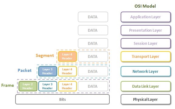
Table of Contents
Computer network communication are a little complex. To understand this communication, experts divides computer network communication into different layers. To do this division, there are two standard models. These models are OSI Model and TCP/IP Model. Both of these models has different layers. OSI Model has 7 layers and TCP/IP model has 4 or 5 layers. Here, we will focus on OSI model layers.
As a beginner in networking, OSI Model and TCP/IP Model are very important to understand the network world. These two common standards has also been a classical question of a network engineer technical interviews. These questions are like: What are the layers of OSI Model? How many Layers does TCP/IP Model has? What is the role of Data Link Layer?, Which devices works on Network Layer? Which protocols are there in Transport layer? etc…
Now, let’s start with the details of OSI Model Layers. In another lesson, we will talk about TCP/IP Model and its layers detailly.
OSI is the abbreviation of Open Systems Interconnection. OSI (Open Systems Interconnection) Model is the first term that a network engineer learn in networking. It is generally the first lesson of almost all the certification courses. It is also generally always encountered especially at the technical job interviews of junior network engineers. But OSI Model is only a visionary concept. In real network operations, you will not think about this standard and its layers.
So, what is this Referance Model? What are these OSI Layers? Below, you can find these layers orderly from starting at the bottom, from Layer 1, to Layer 7, to the top.
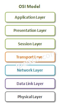
As you can see, there are 7 layers in OSI Reference Model. The first four layers are the Lower Layers and the last three layers are Upper Layers. If we compare OSI (Open Systems Interconnection) and TCP/IP (Transmission Control Protocol/Internet Protocol) Models, Lowers layers of these models has some differences, but the application layer of TCP/IP model is similar to the upper layers od OSI model.
So, whats are the roles of each OSI Model Layer? Lets talk about them one by one detailly
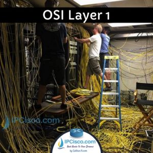
OSI Physical Layer (Layer 1) is the actual connectivity between the source and the destination. It is the layer in which the physical characteristic of the network is defined and bit flow transfer is done. These bits are determined with signals. These signals can be both analog and digital. Electrical signals are used for fixed connections and radio signals are used for wireless connections.
In other words, bit flow is done in this level, in other words meaningful 0 and 1 bits are transferred here. Basically, it is the layer in which bit streams are transferred over different media types. Network cabling, different types of cables and network connectors are on physical layer in OSI Model.
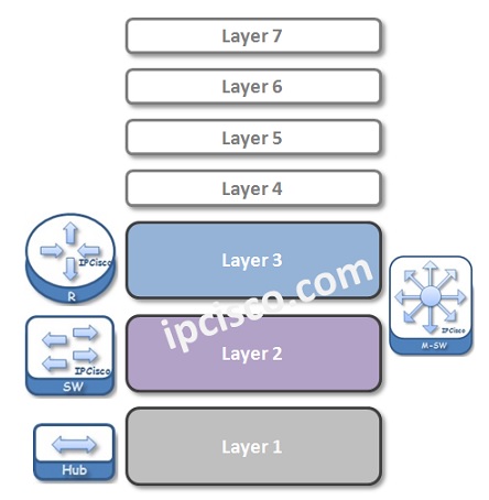
As a simple and old network equipment, simple hubs works in physical layer (layer 1). Because, there are not smart devices and on layer 1, there is no need for a smart device.
Below, you can find operation examples in Layer 1. The upper two are a little complex but the lower two can be a good examples:)


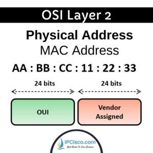
OSI Data-link Layer (Layer 2) is the medium provision Layer. It defines how data is formatted for the transmission over physical medium. Layer 2 provides, node-to node connectivity. It is also the layer of physical MAC addresses.
The most important devices work on layer 2 of OSI Model is Layer 2 switches. As a network engineer, a network technician or a network admin, you will work on these data-link layer devices too much.
Data Link Layer encapsulates the data by adding a layer 2 header and layer 2 trailer. The data after adding Layer 2 Header and layer 2 trailer is called “frame”. Layer 2 header contains source and destination MAC Addresses. So, it is responsible to find the next destination in the network. For decapsulation, it also removes these header and trailer and sends the data to the upper network layer.
Data Link Layer provides Error-free transfer of different categories of data frames. It detects physical layer errors and corrects them.
Different network protocols and standards are used in the different layers of OSI model. You can think them as the groups of rules. According to these protocols and standards, network technologies are used and device configurations are done.
Ethernet is one of the most popular protocol in data link layer. Ethernet is the general name of the standard which is used in our home or office networks. It defines a lot of things like cable types, data speed etc.
There are other protocols and standards in data link layers. Some of them are: PPP, HDLC, FDDI, ATM, Frame Relay.
Data-link Layer has two sub-layers. These layers are:
The MAC Sub Layer controls how a computer on the network gains access to the data and permission to transmit it. And it carries the physical address of each device on the network.
The Logical Link Control (LLC) responsible for managing frames to upper and lower layers, Flow control mechanism and Error checking.

OSI Model Network Layer is the layer of logical addressing. This layer decides the logical address of the destination with IP addresses. By doing this, it connects different networks that use different medias each other. These addresses can be IPv4 address or IPv6 address.
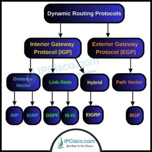
Network layer is also responsible for routing. With routing, it decides the path of the packets through the network. In other words, it defines the routers that the data will go through. This is one of the popular areas for network engineers :) So, routing protocols works on layer 3 (network layer).
A Layer 3 Header (IP Header for IP) is added to the data in this layer. After this addition, frame is called as “packet”. In this header also the next level protocol is mentioned. It can be any transport layer protocol like, TCP, UDP and SCTP.
Frame fragmentation is also done in this Layer. If a frame is longer than MTU (Maximum Transmission Unit), then it is fragmented (divided to the little packets).
There are different protocols used in network layer of OSI. Some of these protocols are IPv4, IPv6, ICMP, IPSec, OSPF, BGP etc.

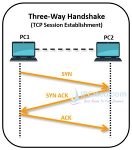
Transport Layer (Layer 4) establishes, maintains and manages end to end secure connection. This layer allows multiple transports on same physical connection.
Transport layer is responsible for end-to-end Error Recovery and Flow Control. Transport Layer is also the Layer that QoS facilities also performed.
Different transport layer protocols are used in this layer. According to used Layer 4 protocol, Layer 4 Header is added to the packet in this Layer. After this the packet called “segment”.
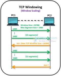
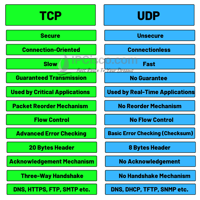
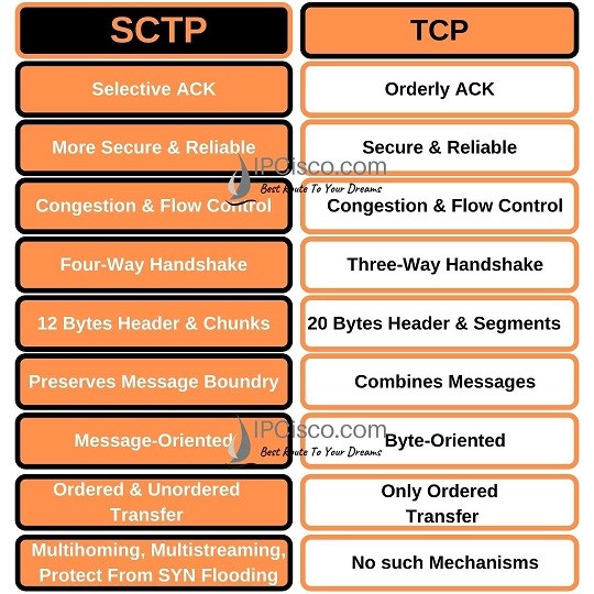
There are two common Transport Layer Protocols. These Protocols are UDP (User Datagram Protocol) and TCP (Transmission Control Protocol). There are also other Transport Layer Protocols like SCTP, RSVPetc. But in CCNA, we will focus on TCP and UDP. We will explain the details of these protocols in the following lessons.
Below, you can find some of TCP layer 4 operations and transport layer protocols comparison.
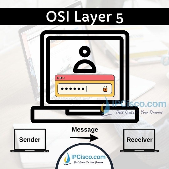
Session Layer (Layer 5) is the OSI layer, that responsible for session jobs between the end points. It provides session establishment, maintenance and termination. Logging is also done in this layer. One of the other main roles of this session layer is multiplexing transport layer services.
Session layer is mainly used by applications themselves. So, network engineers do not work on this layer. This is the job of application developers.
Log in to a computer for file transfer can be an example of session layer job.
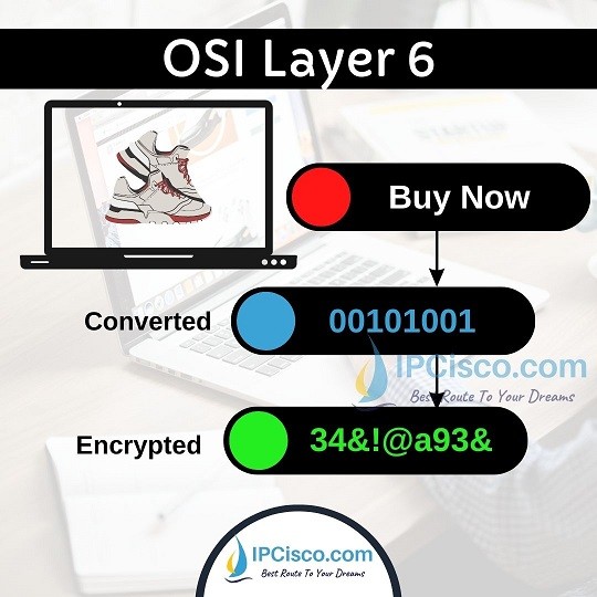
Presentation Layer (Layer 6) is the Translator of the network. There are many data formats in any network. This layer provides translation between different formats.
For example, image formats like jpeg, gif, voice formats like mp3 and video format like mp4 are all need different behaviors. Presentation layer converts this different data into a readable format.
Encryption and compression of the data are also done in presentation layer (layer 6) of OSI Model.
Application Layer (Layer 7) is the closest layer to user. It is the interface between applications and the underlying Layers. It provides the provision of the communication between Applications. Application Layer let programs to reach different network resources.
Some of the protocols used in Application Layer are Telnet, FTP, SMTP, HTTPS, SSL, SNMP etc. Different services work with these protocols. For example, the browser that you use internet, works with HTTP. By the way, the application itself is not belong to this layer.

As you know in a network there are some common network devices like Hubs, Repeaters, Bridges, Switches and Routers. These devices operates in different Layers of OSI model. Lets check this devices and the Layers they are used.
Everything begins with the data at the Application Layer. Then through out the destination, in each Lower Layer, an additional Header is added to these Data. And at the Physical Layer, all these are send via 1s and 0s as voltages over the cables.
What are these Headers of OSI Model Layers and how effects the data?
There are seven layer in OSI Reference Model.
7 layers of OSI are given below:
Physical layer is responsible with cabling, bits and volts.
TCP and UDP are OSI transport layer protocols. They work at layer 4 of OSI model.
Routers works on layer 3, OSI model network layer.
Simple switches are also called layer 2 switches. They work at layer 2, data link layer of OSI.
Physical layer, data-link layer, network layer and transport layer are the lower layers of OSI Model.
Session layer, presentation layer and application layer are the upper layers of OSI Model.
FTP, HTTP and DNS are application layer protocols. They work at application layer, layer 7.
Routing protocols like OSPF, EIGRP, BGP works on layer 3, network layer.


Leave a Reply