- COURSES
- SPECIALS
- BLOG
- MEMBERS
- SHOP
- BOOKSHELF
- ABOUT
- ENROLL HERE
VLAN (Virtual LAN) is one of the most important Layer 2 technology in networking. Network engineers and network admins works on VLANs and do VLAN configuration a lot. So, about this important lesson, we have created multiple VLAN Configuration Examples on Cisco Packet Tracer. Before, we have explained VLAN configuration with multiple packet tracer configuration examples. Here, we will do another packet tracer VLAN example to learn VLANs better.
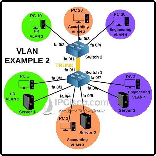
For our Cisco Packet Tracer VLAN Example 2, we will use the below VLAN Example topology. Here, we have one switch, one router and three VLANs in the switch. In every VLAN, there are two host devices, a PC and a server. VLANs are belong to different departments like HR, Engineering and Accounting.
To Practice More On Cisco Packet Tracer, You Can Start Our Cisco Packet Tracer Labs Course.
To do this Packet Tracer VLAN Configuration, we will follow the below configuration steps one by one.
You Can Check Other Packet Tracer Configuration Examples. Some of Them Are:
Cisco Packet Tracer DHCP Configuration
Packet Tracer IPv6 Configuration Example
Cisco Packet Tracer VTP Configuration
Packet Tracer SSH Configuration
Table of Contents
The first step of Cisco Packet Tracer VLAN configuration is IP addressing. To do this, we will use the below ip addresses:
The second step of Cisco Packet Tracer VLAN Example 2 is creating the VLANs on Switch 1. To do this we will use “vlan vlan-id”. And after that we will name these vlans with “name vlan-name” command. We will do this for three VLANs on Cisco switch.
Switch 1# configure terminal
Switch 1(config)# vlan 2
Switch 1(config-vlan)# name HR
Switch 1(config-vlan)# vlan 3
Switch 1(config-vlan)# name Accounting
Switch 1(config-vlan)# vlan 4
Switch 1(config-vlan)# name Engineering
Switch 1(config-vlan)# exit
Thirdly, we will assign ports to the VLANs on switch 2. As you can see on the above VLAN topology, the ports are VLANs are like below:
Now, let’s do this configuration on Cisco Packet tracer on the switch.
Switch 1(config)# interface fa0/2
Switch 1(config-if)# switchport mode access
Switch 1(config-if)# switchport access vlan 2
Switch 1(config-if)# interface fa0/3
Switch 1(config-if)# switchport mode access
Switch 1(config-if)# switchport access vlan 2
Switch 1(config-if)# interface fa0/4
Switch 1(config-if)# switchport mode access
Switch 1(config-if)# switchport access vlan 3
Switch 1(config-if)# interface fa0/5
Switch 1(config-if)# switchport mode access
Switch 1(config-if)# switchport access vlan 3
Switch 1(config-if)# interface fa0/6
Switch 1(config-if)# switchport mode access
Switch 1(config-if)# switchport access vlan 4
Switch 1(config-if)# interface fa0/7
Switch 1(config-if)# switchport mode access
Switch 1(config-if)# switchport access vlan 4
After assigning access ports to VLANs, now, we will configure trunk port on Cisco Switch 1 on packet tracer. We will set fast ethernet 0/1 interface as vlan trunk port. To do this on packet tracer, we will use the below configuration commands. Here, the key command is “switchport mode trunk” commands. This will set the port as trunk port. After that we will use “switchport nonegotiate” command not to negotiate this. Then we will set the encapsulation type as dot1.q. We will also set negotiation for this.
Switch 1(config-if)# interface fa0/1
Switch 1(config-if)# switchport mode trunk
Switch 1(config-if)# switchport nonegotiate
Switch 1(config-if)# switchport trunk encapsulation dot1.q
Switch 1(config-if)# switchport trunk encapsulation negotiate
Here, we will also configure the Native VLAN as VLAN 5. We will also set allowed VLANs. To do this we can allow all VLANs or we can specify the allowed VLANs one by one.
Switch 1(config-if)# switchport trunk native vlan 5
Switch 1(config-if)# switchport trunk allowed vlan all
Or
Switch 1(config-if)# switchport trunk allowed vlan 2,3,4,5
We have configured Switch 1 on Cisco packet tracer. Now, it is time to configure Switch 2. We will create VLANs on switch 2.
Switch 2# configure terminal
Switch 2(config)# vlan 2
Switch 2(config-vlan)# name HR
Switch 2(config-vlan)# vlan 3
Switch 2(config-vlan)# name Accounting
Switch 2(config-vlan)# vlan 4
Switch 2(config-vlan)# name Engineering
Switch 2(config-vlan)# exit
On Switch 2, we will also assing the access ports to VLANs like below:
Now, let’s do the configuration on Switch 2, on Cisco Packet tracer.
Switch 2(config)# interface fa0/2
Switch 2(config-if)# switchport mode access
Switch 2(config-if)# switchport access vlan 2
Switch 2(config-if)# interface fa0/3
Switch 2(config-if)# switchport mode access
Switch 2(config-if)# switchport access vlan 3
Switch 2(config-if)# interface fa0/4
Switch 2(config-if)# switchport mode access
Switch 2(config-if)# switchport access vlan 4
Like we have done on switch 1, we will also do the same trunk configuration on switch 2. Again, we will use fast ethernet 0/1 as vlan trunk port. To do this, we will use similar vlan trunk configuration commands on cisco packet tracer.
Switch 2(config-if)# interface fa0/1
Switch 2(config-if)# switchport mode trunk
Switch 2(config-if)# switchport nonegotiate
Switch 2(config-if)# switchport trunk encapsulation dot1.q
Switch 2(config-if)# switchport trunk encapsulation negotiate
We will set the same Native VLAN and same allowed VLANs on Switch 2. Native VLAN is VLAN 5 and allowed VLANs are all or VLANs 2,3,4,5.
Switch 2(config-if)# switchport trunk native vlan 5
Switch 2(config-if)# switchport trunk allowed vlan all
Or
Switch 2(config-if)# switchport trunk allowed vlan 2,3,4,5
At the last step of Packet Tracer Cisco VLAN Configuration example, we will use basic ping. We will do this in four steps:
Simply, we will ping;
In Cisco Packet Tracer VLAN 2 Example, we have configured a different VLAN topology. VLANs are very important for a network engineer. You will work on them both in real life and on network certifications like Cisco CCNA, CCNP ENCOR, CCIE etc. So, learning VLAN lesson will help you a lot!


Leave a Reply