- COURSES
- SPECIALS
- BLOG
- MEMBERS
- SHOP
- ABOUT
- ENROLL HERE

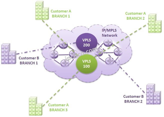
Nokia VPLS (Virtual Private LAN Service) is a Multipoint-to-Multipoint Layer 2 VPN Service that connects multiple branches of a Customer, in a single logical switched architecture over Service Provider IP/MPLS network. This is basically VPLS in networking or VPLS meaning. Service Provider IP/MPLS network is our transit network here. Different brances of a customer, pass through this IP/MPLS network and this Layer 2 VPN infrastructure seems to the customer as their branches are connected to a single LAN Switch.
You can also check Nokia VPLS Configuration and Cisco VPLS Configuration on IPCisco.com.
With such an IP/MPLS network, Service Provider (ISP) can use this Layer 2 VPN infrastructure times and times for different customers. Different customer branches can communicate over Service Provider IP/MPLS network without a conflict. This is the key point of Virtual Private LAN Service architecture (Layer 2 VPN).
In the following lessons, we will learn How to Configure VPLS and other key lessons like VPLS Topologies, MAC Learning and Labelling. Now, let’s continue to basic of this Nokia VPN Service.
With Nokia Virtual Private LAN Service solution, customers has a cheap and effective way to communicate their branches. They can easily add new brances to their logical switched L2 VPN network. They do not need to know WAN devices. All the transport responsibility is belong to Service Provider (ISP). Customer is only responsible with its own routing. Remember, they only buy a “logical switched architecture” from the ISP.
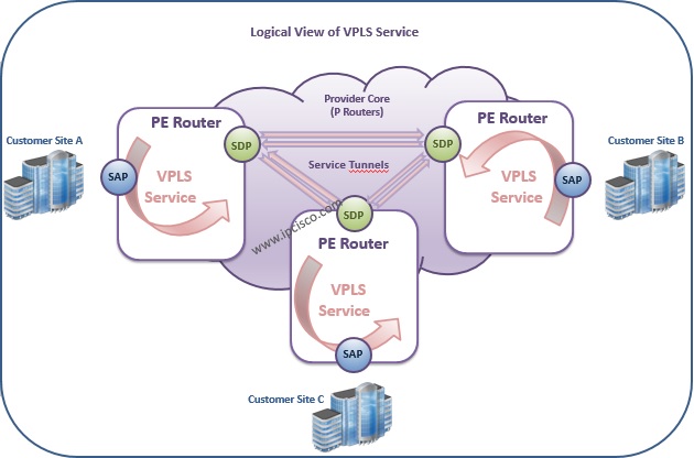
You can see the Logical view of VPLS below:

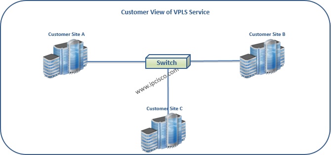
From the customer perspective, with Layer 2 VPN, the sites of the customer are like, they are connected to an Ethernet Switch in its own LAN. So, in this Nokia L2 VPN Service, Switching is the main point.
You can see Layer 2 VPN, Virtual Private LAN Service from the customer point of view like below:

By using Virtual Private LAN Service, there can be many private LANs in the Service Provider MPLS Network. Each of these LANs (VPLSes) are unaware eachother. There is no conflict. Because these Virtual Private LAN Service differ with Service IDs in service provider network.
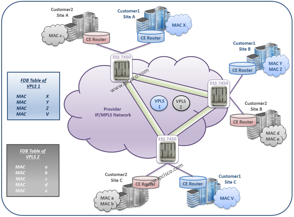
Every process is like in an Ethernet Switch in Virtual Private LAN Service architecture. Like ethernet switches, MAC addresses are important because of the fact that Virtual Private LAN Service works on Layer 2. MAC Address Learning and the forwarding process is done according to the tables in which MAC-address and port information is kept. This table is Forwarding Database (FDB). In FDB, the mac addresses are associated with SAPs and SDPs. And then, the traffic is switched according to the Forwarding Databases (FDB).
MAC Learning is done with the same mechanism that is used in Ethernet Switches. Think about this, VPLS in networking is like a mini switch in the Servis Router. This mini switch sends the packets to its destination if it knows its Destination MAC Address. If not, it forwards the traffic through all the ports. This is flooding mechanism like in Ethernet Switches.
In VPLS, the mechanism is similar. At the beginning there is no record in Forwarding Databases (FDB). So, if a packet received from a SAP or a SDP, then it is flooded through all SAPs and SDPs. Because there is no record about the destination. But whenever any packet received by a SAP or a SDP, the mac address of the sending node is recorded under this SAP or SDP. The Forwarding Databases (FDB) is filled with such traffic. And whenever a packet whose destination is also recorded in FDB, is directly sent to that SAP or SDP. In other words, if there is a record about the destiantion, it is sent directly to that destination with the help of FDB. If there is no record, then it is flooded.

FDB(MAC Table) of VPLS
In Layer 2 VPN Architecture, all the nodes are connected via pseudowires as fully mesh. Each Virtual Private LAN Service has a specific VC-ID or Pseudowire ID and this differentiate one VPN Service to other VPN Services. So, VPLS services in the service provider network do not conflict.
So, how many connections are required for a VPLS topology? To determine this, we use the formula of mesh connections. This is n * (n-1) / 2. For each VPLS n * (n-1) / 2 pseudowire is required for full mesh connection. Here, n is the number of your nodes.
Full mesh requirement is for normal L2 VPN Architecture. For Hierarchical Virtual Private LAN Service (H-VPLS) there is no such requirement. We will talk about H-VPLS, in another lesson. You can also check Hierarchical VPLS (H-VPLS) to learn more about it.
Here, we have talked about basic overview of Virtual Private LAN Service. In the following lessons, we will talk about Virtual Private LAN Service Topologies, VPLS MAC Learning, VPLS Labelling and VPLS Configurations detailly.
You can also visit VPLS Configuration Cisco example to learn how to configure this service on Cisco routers.
Leave a Reply