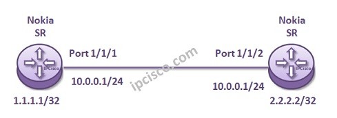
In this lesson, we will focus on
Nokia LDP Configuration on
Nokia Service Routers. To do an
LDP Configuration Example , we will use the below basic topology. Here, we will configure these two routers to become an
LDP peer and
establish an
LSP session.

LDP Configuration Example Topology
Configuration on Router A
A:RouterA>config>router #
			interface “to_RouterB”
				address 10.0.0.1/24
				port 1/1/1
				exit
			interface “system”
				address 1.1.1.1/32
				exit
			exit
A:RouterA>config>router>ldp#
			interface-parameters
				interface “to_RouterB”
				exit
			exit
Configuration on Router B
B:RouterB>config>router #
			interface “to_RouterA”
				address 10.0.0.2/24
				port 1/1/2
				exit
			interface “system”
				address 2.2.2.2/32
				exit
			exit
B:RouterB>config>router>ldp#
			interface-parameters
				interface “to_RouterA”
				exit
			exit
Here, I would like to inform you about an important point. LDP sessions established between “transport addresses” of the routers. In Nokia Service Routers, this transport addresses are “system addresses”. The session is established between these system addresses. So, before LDP neighbour discovery, system addresses must be configured.


Leave a Reply