- COURSES
- SPECIALS
- BLOG
- MEMBERS
- SHOP
- ABOUT
- ENROLL HERE

Table of Contents
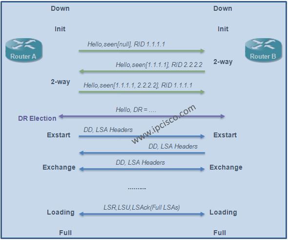
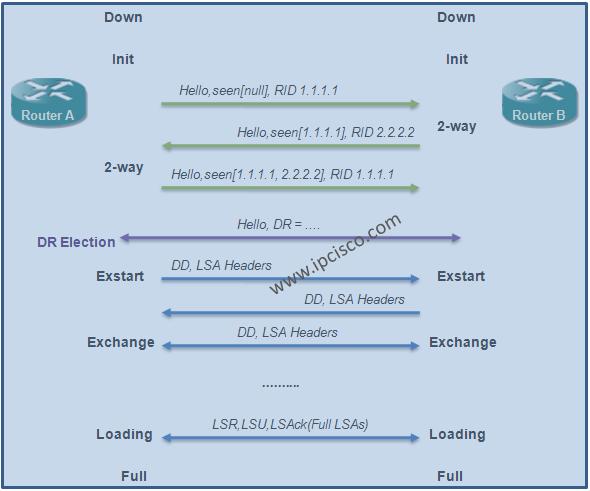
For OSPF operation, firstly OSPF Neighborship in other words OSPF Adjacency is established between OSPF routers. To do this, these OSPF routers must be on the same link. Beside being in the same link, these routers need to use some messages and folllow some steps for this neighborship. These steps are calles OSPF States.

At the beginnning, to establish OSPF neighborship, Hellos messages are sent to OSPF All Routers multicast address, 224.0.0.5. Each of these Hellos include Router IDs and the other parameters that are required for neighborship. The beginning OSPF State is Init State and after Hello messages are sent and the parameter check mutually, 2-way adjacency is established. Anymore, these routers are neighbors and they can share their LSDBs.
After this state, the next step is Exstart State in which Link-State Databases (LSDBs) will be shared. Here, firtly, Database Description (DD) packets that include LSA lists are sent. After controlling these lists, routers requests the missing LSA in their list. This state is Exchange State anymore.
You can also learn OSPF LSA Types
For the equalisation of LSDBs, LSR and LSU messages are sent. The missing LSAs are requested with LSR messages. As a response, these LSAs are sent via LSU messages. This state is Loading state. And this step continues until Full state in which the databases are equal. In full states, the topology databases are equal in both OSPF neighbor.
After Full State, there are some maintanenca processes in OSPF neighbourship. First of all this neighbourship needs to be up all the time. To check this neighborship, the state of the link is controlled with two different timer. These timers are Hello Interval and Dead Interval. Every OSPF neighbor waits a Hello message from its neighbor in the Hello Interval and it do not receive any Hello message in the Dead Interval, it announce that this neighborship is down.
Beside this neighborship check, there can be any change in the network in this period. These changes must be sent with LSAs to the neighbor routers. Beside this triggered updates, there are also periodic LSA updates. With these updates topology databases continue to be identical in both ends.
You can also learn How to Configure OSPF on Cisco Routers
The summary of these OSPF states are given below:
Basically, the states of OSPF neighbour adcajency are like above. During these OSPF States, there is an important process called “DR and BDR Selection“. Let’s talk about, how is these selection is done.
DR (Designated Router) and BDR (Backup Designated Router) are the two routers elected in the Multi-Access OSPF network, that works as Master and Backup. Here, the Multi-Access word is important. Because there is no DR and BDR selection in point-to-point networks. After the election in Multi-access networks, DR and BDR is determined. The other remainning routers in OSPF network are called as Non-DR. So, why we use DR and BDR in OSPF networks?
DR and BDR works as a central node and its backup in OSPF network. All the updates come firstly here and then they are sent to the Non-DRs from here. If there is no such a mechanism, routers must connected together as full mesh. And this can cause a high LSA traffic. So, with DR and BDR mechanism, we avoid this LSA traffic.
On a Multi-Access network, routers form Full adjacency with DR (Designated Router) and BDR (Backup Designated Router). Other routers which are called Non-DRs, form 2-Way adjacency between them. They do not need to finish all the states and go to the full adjacency.
DRs are chosen based on the priority value. The default priority is 1. And therouter that has the highher priority value is choosen as the DR. If the priority value is set to 0 manually, this means that, this router can not be a DR.
You can also learn OSPF Authentication, Virtual Links and Timers
In DR and BDR mechanism, if any other router comes up with a better priority value, or if we change the priority valur of an existing router, DR and BDR is not change. To do a new election, DR and BDR must be down.
The updates about a link is sent to the multicast address 224.0.0.6. This is the all DRs address. After getting this update, DR send this update to 224.0.0.5, all OSPF routers address. After that all the routers are avare of this information.
You can also check other Cisco CCNP ENCOR certification lessons
Leave a Reply