If you are preparing for Cisco CCNA exam, learning theory alone is not enough. Packet Tracer labs help you practice real networking scenarios, improve troubleshooting skills, and understand how Cisco networks actually work. In this post we will focus top 3 important packet tracer labs for CCNA (Cisco Certified Network Associate). We will configure Cisco routers and switches for 3 important CCNA Lessons. These three lessons are: VLANs, OSPF and DHCP Configurations.
Table of Contents
Why These Packet Tracer Labs Are Important?
Packet Tracer labs are one of the most effective ways to prepare for the CCNA exam because they help students move beyond theory and practice real networking skills. By working with switching, routing, VLANs, OSPF, DHCP and troubleshooting scenarios, learners can understand how Cisco networks operate in real environments. These CCNA Packet Tracer labs also improve problem-solving skills, hands on experience on Cisco configurations and troubleshooting capabilities, which are essential skills for both the certification exam and real-world networking jobs.
VLAN and Inter-VLAN Routing Lab
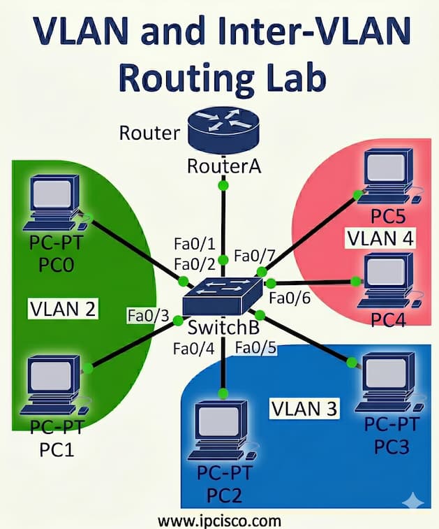
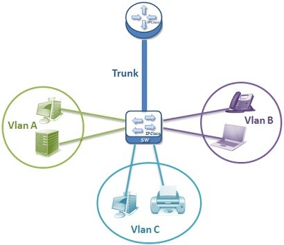
VLAN and Inter-VLAN Routing configurations are among the most important topics in the CCNA certification. In this Packet Tracer lab, students learn how to separate networks into different VLANs, configure trunk links between switches and enable communication between VLANs using Router-on-a-Stick. These CCNA Packet Tracer labs also improve problem-solving and troubleshooting capabilities, which are essential skills for both the certification exam and real-world networking jobs.
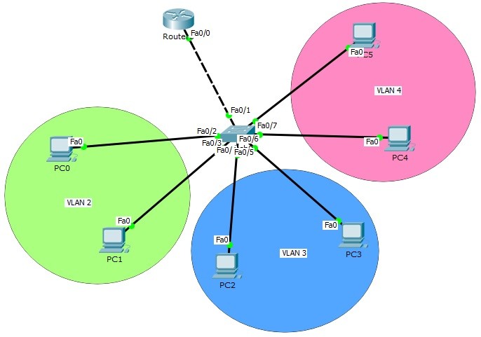
For our first packet tracer lab, we will use the below topology.
Packet Tracer VLAN & Inter VLAN Configuration Example
Creating VLANs
In the first step of our packet tracer VLAN configuration example will creating VLANs. Here, we will create VLAN 2, 3 and 4. Then, we will enter the interface range and configure the interface range as access interface. Lastly, we will assign the interface to a specific VLAN with “switchport access vlan” command.
Switch (config) # vlan 2
Switch (config-vlan) # vlan 3
Switch (config-vlan) # vlan 4
Switch (config-vlan) # exit
Switch (config) # interface range fastEthernet 0/2-3
Switch (config-if-range) # switchport mode access
Switch (config-if-range) # switchport access vlan 2
Switch (config-if-range) # exit
Switch (config) # interface range fastEthernet 0/4-5
Switch (config-if-range) # switchport mode access
Switch (config-if-range) # switchport access vlan 3
Switch (config-if-range) # exit
Switch (config) # interface range fastEthernet 0/6-7
Switch (config-if-range) # switchport mode access
Switch (config-if-range) # switchport access vlan 4
Switch (config-if-range) # exit
We have configured VLANs and associated ports. Now it is time to verify our VLANs.
Switch# show vlan

VLAN Name Status Ports
---- -------------------------------- --------- -------------------------------
1 default active Fa0/8, Fa0/9, Fa0/10, Fa0/11
Fa0/12, Fa0/13, Fa0/14, Fa0/15
Fa0/16, Fa0/17, Fa0/18, Fa0/19
Fa0/20, Fa0/21, Fa0/22, Fa0/23
Fa0/24, Gig0/1, Gig0/2
2 VLAN0002 active Fa0/2, Fa0/3
3 VLAN0003 active Fa0/4, Fa0/5
4 VLAN0004 active Fa0/6, Fa0/7
1002 fddi-default act/unsup
1003 token-ring-default act/unsup
1004 fddinet-default act/unsup
1005 trnet-default act/unsup

AN Type SAID MTU Parent RingNo BridgeNo Stp BrdgMode Trans1 Trans2
---- ----- ---------- ----- ------ ------ -------- ---- -------- ------ ------
1 enet 100001 1500 - - - - - 0 0
2 enet 100002 1500 - - - - - 0 0
3 enet 100003 1500 - - - - - 0 0
4 enet 100004 1500 - - - - - 0 0
Configuring Trunk Ports
After creating VLANs and port VLAN associations, now, we will set trunk port. To do this, we will use “switchport mode trunk” command under the trunk interface.
Switch (config) # interface fastEthernet 0/1
Switch (config-if) # switchport mode trunk
Switch (config-if) # switchport trunk allowed vlan 2,3,4
Switch (config-if) # exit
Router-on-a-Stick Configuration
Now, it is time to configure the most imporant part of this configuration. Wİth this configuratiın, we will set the configuration between VLANs. This is Router on a Stick configuration step of this configuration example. To do this, firstly we will open the physical interface that will works as trunk between the switch and the router. We will do this with “no shutdown” command.
Router (config) # interface fastEthernet 0/0
Router (config-if) # no shutdown
Router (config-if) # exit
After that, under the physicalinterface, we will create sub interfaces. Under each sub interaface, we will set the encapsulation type, allowed vlans on this trunk and the logical ip address with subnet mask.
Router (config) # interface fastEthernet 0/0.2
Router (config-if) # encapsulation dot1q 2
Router (config-if) # switchport trunk allowed vlan 2,3,4
Router (config-if) # ip address 10.0.0.1 255.255.255.0
Router (config-if) # no shutdown
Router (config-if) # exit
Router (config) # interface fastEthernet 0/0.3
Router (config-if) # encapsulation dot1q 3
Router (config-if) # switchport trunk allowed vlan 2,3,4
Router (config-if) # ip address 20.0.0.1 255.255.255.0
Router (config-if) # no shutdown
Router (config-if) # exit
Router (config) # interface fastEthernet 0/0.4
Router (config-if) # encapsulation dot1q 4
Router (config-if) # switchport trunk allowed vlan 2,3,4
Router (config-if) # ip address 30.0.0.1 255.255.255.0
Router (config-if) # no shutdown
Router (config-if) # exit
Now, we will verify Router on a stick configuration on the router.
Router# show ip interface brief
Interface IP-Address OK? Method Status Protocol

FastEthernet0/0 unassigned YES unset up up

FastEthernet0/0.2 10.0.0.1 YES manual up up

FastEthernet0/0.3 20.0.0.1 YES manual up up

FastEthernet0/0.4 30.0.0.1 YES manual up up

FastEthernet0/1 unassigned YES unset administratively down down

Vlan1 unassigned YES unset administratively down down
As you can see, all the subinterfaces that we have created under the physical interface of Cisco router is above.
Inter VLAN Verification
To verify our Router on Stick (Inter VLAN Routing) configuration, simply we will ping from one PC in a VLAN, to another PC in another VLANs.
Let’s do this on PC0. We will ping firstly, PC3 and then PC5.
PC0>ping 20.0.0.3
Pinging 20.0.0.3 with 32 bytes of data:
Reply from 20.0.0.3: bytes=32 time=1ms TTL=127
Reply from 20.0.0.3: bytes=32 time=0ms TTL=127
Reply from 20.0.0.3: bytes=32 time=0ms TTL=127
Reply from 20.0.0.3: bytes=32 time=0ms TTL=127
Ping statistics for 20.0.0.3:
Packets: Sent = 4, Received = 4, Lost = 0 (0% loss),
Approximate round trip times in milli-seconds:
Minimum = 0ms, Maximum = 1ms, Average = 0ms
PC0>ping 30.0.0.3
Pinging 30.0.0.3 with 32 bytes of data:
Reply from 30.0.0.3: bytes=32 time=1ms TTL=127
Reply from 30.0.0.3: bytes=32 time=0ms TTL=127
Reply from 30.0.0.3: bytes=32 time=0ms TTL=127
Reply from 30.0.0.3: bytes=32 time=1ms TTL=127
Ping statistics for 30.0.0.3:
Packets: Sent = 4, Received = 4, Lost = 0 (0% loss),
Approximate round trip times in milli-seconds:
Minimum = 0ms, Maximum = 1ms, Average = 0ms
OSPF Packet Tracer Lab
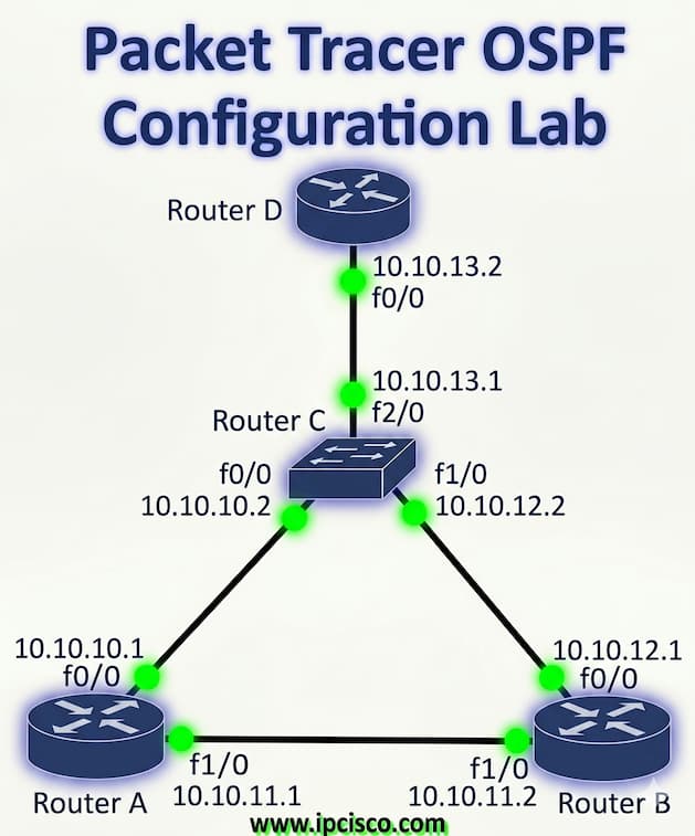
OSPF is one of the most widely used dynamic routing protocols in enterprise networks. In this CCNA Packet Tracer lab, students practice configuring OSPF, advertising networks, establishing neighbor relationships and verifying routing tables. The lab also introduces troubleshooting techniques for routing problems, helping learners understand how routers exchange information and build efficient network paths in real-world environments. Here, we will configure Single Area OSPF, OSPFv2 on Cisco rotuers with packet tracer.
For our OSPF Packet Tracer Lab, we will use the below OSPF Topology.
Packet Tracer OSPF Configuration Example
Enabling OSPF Process
We will start our OSPF Configuration, by enabling OSPF process. To do this, we will use “router ospf ospf-process-number” command. In router A, we will enable OSPF Process, with Process Number “1“. We will do this on other routers also.
A(config)# router ospf 1
A(config-router)#
Adding OSPF Networks Under OSPF Process
After enabling OSPF process on our Cisco Router A, now, we will advertise networks under this OSPF process. We will use “network” command with the advertised network address, wildcard mask and the “area” keyword with “OSPF Area-id“.
A(config-router)# network 10.10.10.0 0.0.0.255 area 0
A(config-router)# network 10.10.11.0 0.0.0.255 area 0
A(config-router)# end
Then, we will save OSPF configuration with “copy running-config startup-config” or “write” commands.
OSPF Configuration on Other Routers
We will do Cisco OSPF configuration also on Router B, Router C and Router D like Router A. We will enable OSPF and then add OSPF Networks under OSPF Process 1.
B(config)# router ospf 1
B(config-router)# network 10.10.11.0 0.0.0.255 area 0
B(config-router)# network 10.10.12.0 0.0.0.255 area 0
B(config-router)# exit
B # copy running-config startup-config
C(config)# router ospf 1
C(config-router)# network 10.10.10.0 0.0.0.255 area 0
C(config-router)# network 10.10.12.0 0.0.0.255 area 0
C(config-router)# network 10.10.13.0 0.0.0.255 area 0
C(config-router)# end
C# copy running-config startup-config
D(config)# router ospf 1
D(config-router)# network 10.10.13.0 0.0.0.255 area 0
D(config-router)# end
D# copy running-config startup-config
Single Area OSPF Verification
We have completed Packet Tracer Single Area OSPF Configuration. Now, it is time to verify our Cisco config. Below, you can find important OSPF verification commands to verify OSPF confgiuration.
- show ip ospf interface
- show ip ospf neighbor
- show ip ospf database
- show ip ospf statistics
- debug ip ospf monitor
- debug ip routing
- show ip ospf packet
- debug ip ospf adj
- debug ip ospf events
- show ip ospf virtual-link
- show ip ospf neighbor
Router DHCP Server Configuration Lab
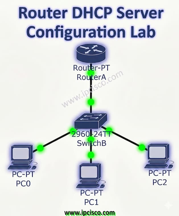
Dynamic Host Configuration Protocol (DHCP) is one of the most important network services used to automatically assign IP addresses to devices in a network. In this Packet Tracer DHCP lab, we will configure Cisco DHCP step by step, assign IP addresses dynamically, and verify DHCP communication between routers and clients.
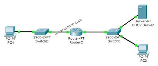
For our Packet Tracer Router DHCP Configuration Example on Cisco routers, we wil use the below topology. In this packet tracer example, we will configure DHCP Server in one broadcast domain. So, we will not need ip-helper address command to broadcast DHCP traffic.
Packet Tracer DHCP Server Configuration Example
Router Interface Configuration for DHCP Server
On routerA, firstly we will give an ip address to the router interface that is connected to the switch. This is basically interface ip address configuration.
RouterA# config terminal
RouterA(config)# interface fastEthernet 1/0
RouterA(config-if)# ip address 192.168.10.1 255.255.255.0
RouterA(config-if)# no shut

%LINK-5-CHANGED: Interface FastEthernet1/0, changed state to up
%LINEPROTO-5-UPDOWN: Line protocol on Interface FastEthernet1/0, changed state to up<
Creating DHCP Pool
Secondly, we will create a DHCP pool named IPD. In this ip dhcp pool we will mention ip addresses that will be given to the DHCP clients.
RouterA(config-if)# exit
RouterA(config)# ip dhcp pool IPD
RouterA(dhcp-config)# network 192.168.10.0 255.255.255.0
Setting Default Router and DNS Server Addresses
In this step, we will assign the router’s interface address as a default-router address for clients. We will also set DNS Server address for this configuartion.
RouterA(dhcp-config)# default-router 192.168.10.1
RouterA(dhcp-config)# dns-server 4.4.4.4
RouterA(dhcp-config)# exit
Excluding IP Addresses From DHCP Pool
In this step, we will exclude some addresses, we will do DHCP excluded‑address configuration. Here, we will use with “ip dhcp excluded address” command, that we don’t want to use during this dynamic ip assignments. With “ip dhcp excluded address” command, the mentined addresses will not used in ip dhcp pool.
RouterA(config)# ip dhcp excluded-address 192.168.10.1 192.168.10.10
RouterA(config)# ip dhcp excluded-address 192.168.10.12 192.168.10.14
Router DHCP Server Verification
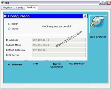
After this configuration, when we check the ip address of PC0, we will see the ip address 192.168.10.11 . Because it is the first available address in DHCP pool.
More Packet Tracer Labs
Hands on experience is very improrant for a network engineer, especially for CCNA Students. To practice on Cisco routers and switches, you can practice with other packet tracer lab lessons. To do this, you can start our Cisco Packet Tracer Labs Course that covers both CCNA and CCNP ENCOR labs.
DOWNLOAD 45 +Packet Tracer Labs!


Gokhan Kosem is a Network Engineer, Instructor and the Founder of IPCisco.com with 15+ years of experience in Cisco, Nokia, Huawei, Juniper, Linux, Service Provider Networks, Routing and Switching technologies.
He has worked on the backbone networks of major service providers and network vendors including Nortel, Alcatel-Lucent (Nokia) and has extensive hands-on experience with Cisco, Huawei, Juniper and Nokia networking technologies.
He has trained thousands of networking students worldwide through IPCisco.com, Udemy, books, labs, quizzes, and educational content across multiple social media platforms.
IPCisco.com | Best Route to Your Dreams


Leave a Reply