- COURSES
- SPECIALS
- BLOG
- MEMBERS
- SHOP
- BOOKSHELF
- ABOUT
- ENROLL HERE

Table of Contents
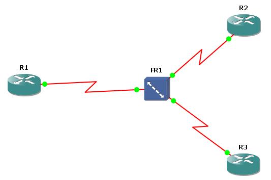
As you know Frame-Relay is a well-known legacy WAN technology that is generally used for backbone routers. In this lesson, we will focus on Frame Relay Point-to-Point Configuration on Cisco routers. To understand the basic configuration of Frame-Relay, we will do a configuration example. We iwll use the below frame-relay topology consist of three Cisco 3600 Series Router and one Frame-Relay Switch.
First of all, we will start with Frame-Relay Switch. On GNS3 create a Frame-Relay Switch and right click the Frame-Relay Switch. Configure the DLCI – port mapping like below:
After mapping, connect the routers to the Frame-Relay Switch port mentioned in the mapping via serial connection. ( R1 to port 1, R2 to port 10, R3 to port 11)
Cisco Point-to-Point Frame Relay Configuration
It is time to configure our routers. Starting with the R1 make the below configuration. Here, the Hub Router is R1.
Firstly we will set up Frame Relay point-to-point subinterfaces on router R1 for efficient WAN communication. Firstly, console logging is disabled to prevent unnecessary output. Then Serial 0/0 interface will be enabled with Frame Relay encapsulation with encapsulation frame-relay command. Then, we will create two point-to-point subinterfaces (s0/0.1 and s0/0.2), each will be assigned to a unique IP address from different /30 subnets. These subinterfaces are mapped to specific DLCIs (101 and 102) with frame-relay interface-dlci dlci command, establishing dedicated virtual circuits for each connection. This approach simplifies routing, avoids split-horizon issues and ensures clear separation between links. Finally, we will save the configuration.
R1(config)# no logging console
R1 (config)# int s 0/0
R1 (config-if)# no shut
R1 (config-if)# encapsulation frame-relay
R1 (config-if)# interface s0/0.1 point-to-point
R1 (config-subif)# ip address 192.168.100.1 255.255.255.252
R1 (config-subif)# frame-relay interface-dlci 101
R1 (config-fr-dlci)# exit
R1 (config-subif)# interface s0/0.2 point-to-point
R1 (config-subif)# ip address 192.168.100.5 255.255.255.252
R1 (config-subif)# frame-relay interface-dlci 102
R1 (config-fr-dlci)# exit
R1 (config-subif)# write
Now, let’s configure R2 for Frame-Relay. Here you can get help from show frame-relay pvc command. This command displays information about Frame Relay Permanent Virtual Circuits (PVCs). It helps you verify the status and performance of each PVC configured on the router. It shows the below information:
Under Cisco Router R2, we will do the below Cisco Frame-Relay Configuration.
R2 (config)# no logging console
R2 (config)# int s 0/0
R2 (config-if)# no shut
R2 (config-if)# encapsulation frame-relay
R2 (config-if)# interface serial 0/0.1 point-to-point
R2 (config-subif)# ip address 192.168.100.2 255.255.255.252
R2 (config-subif)# do show frame-relay pvc
DLCI = 202, DLCI USAGE = UNUSED, PVC STATUS = INACTIVE, INTERFACE = Serial0/0
R2 (config-subif)# frame-relay interface-dlci 202
R2 (config-subif)# do show frame-relay pvc
DLCI = 202, DLCI USAGE = LOCAL, PVC STATUS = ACTIVE, INTERFACE = Serial0/0.1
“do show frame-relay pvc” : Shows which DLCI you will configure to that way, It is very useful for real configurations.
R2 # ping 192.168.100.1
R2 # write
Lastly, we will configure Frame-Relay on R3 like below.
R3 (config)# no logging console
R3 (config)# int s 0/0
R3 (config-if)# no shut
R3 (config-if)# encapsulation frame-relay
R3 (config-if)# interface serial 0/0.1 point-to-point
R3 (config-subif)# ip address 192.168.100.6 255.255.255.252
R3 (config-subif)# do show frame-relay pvc
R3 (config-subif)# frame-relay interface-dlci 203
R3 # ping 192.168.100.5
R3 # show cdp neighbor
R3 # write
After all the configurations done, you can check the connection between routers with the below ping commands. And you also check the frame-relay pvc on R1.
R1 # show frame-relay pvc
R1 # ping 192.168.100.2
R1 # ping 192.168.100.6
Download GNS3 Basic Frame Relay Point-to-Point Configuration Lab.
DLCI (Data-Link Connection Identifier) is a number used in Frame Relay networks to identify a virtual circuit between two devices. DLCI is like a label that tells the router which path to use to send data across a Frame Relay cloud.
PVC (Permanent Virtual Circuit) in Frame Relay is a pre-established, always-available virtual connection between two network devices. PVC is called “permanent” because it is configured by the service provider and stays active without needing to be set up each time data is sent.
Frame Relay connections are mainly divided into two types: Permanent Virtual Circuits (PVCs) and Switched Virtual Circuits (SVCs). Additionally, they can be configured as point-to-point or multipoint connections on routers.


Leave a Reply