- COURSES
- SPECIALS
- BLOG
- MEMBERS
- SHOP
- BOOKSHELF
- ABOUT
- ENROLL HERE
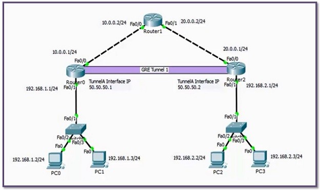
Table of Contents
In this confgiuration example, we will see how to configure Cisco GRE (Generic Routing Encapsulation) Tunnel with Packet Tracer. For our GRE Tunnel Configuration example, we will use the below topology and the given IP addresses.
iYou can DOWNLOAD the Cisco Packet Tracer example with .pkt format At the End of This Lesson.
You can also DOWNLOAD all the Packet Tracer examples with .pkt format in Packet Tracer Labs section.
Here, we assume that all the IP Configurations have been done and we will focus only GRE Tunel Configuration with Packet Tracer. Let’s start with Router 0.
In Router 0, we will create the Tunnel interface and then give this interface an IP Address. After that, we we will define the Tunnel Source, with IP Address or with Interface name. Here, we used Interface name. Lastly, we define the Tunnel Destination IP address.
R0(config)# interface Tunnel 1
R0(config-if)# ip address 50.50.50.1 255.255.255.0
R0(config-if)# tunnel source FastEthernet 0/0
R0(config-if)# tunnel destination 20.0.0.1
R0(config-if)# end
R0# copy running-config startup-config
Now, let’s configure Router 2. We will do the same configuration on Router 2, only IP addresses will change.
R2(config)# interface Tunnel 1
R2(config-if)# ip address 50.50.50.2 255.255.255.0
R2(config-if)# tunnel source FastEthernet 0/0
R2(config-if)# tunnel destination 10.0.0.1
R2(config-if)# end
R2# copy running-config startup-config
After Tunnel configuration, we need to write a Static Route on Router 0 and Router 2. Because, the routers need to know how to reach to the users connected to the other end router. In other words, because of the fact that the other end LAN is not directly connected to the router, it needs routing information and we provide this with a Static Route.
R0(config)# ip route 192.168.2.0 255.255.255.0 50.50.50.2
R0(config)# end
R0# copy running-config startup-config
R2(config)# ip route 192.168.1.0 255.255.255.0 50.50.50.1
R2(config)# end
R2# copy running-config startup-config
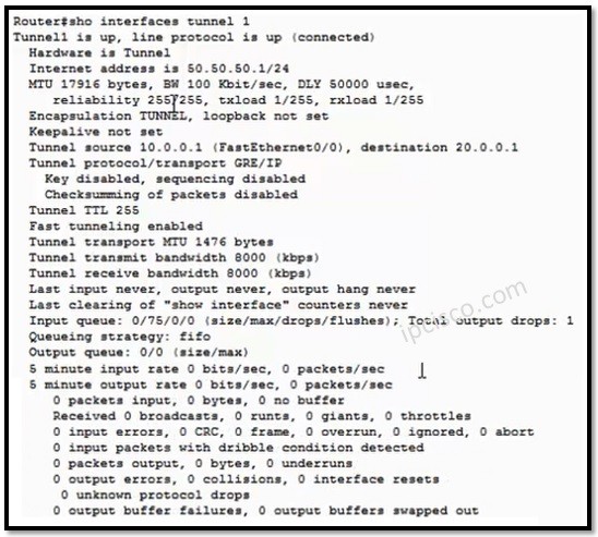
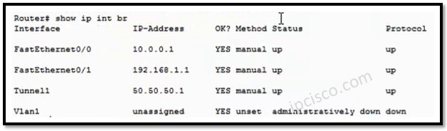
Now, it is time to verification. Let’s verify our GRE Tunnel Configuration. For Tunnel verification, we can use the “show interface tunnel 1” command. And for the IP addresses of Tunnels with other IP interfaces, we can use “show ip interfaces brief” command.
R0# show interfaces tunnel 1
R0# show ip interface brief
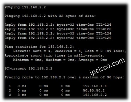
After this verification, we can use “ping” and “tracert” commands on PCs, to reach to the other end.
PC0> ping 192.168.2.2
PC0> tracert 192.168.2.2
PC3> ping 192.168.1.3
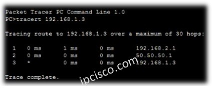
PC3> tracert 192.168.2.2
You can DOWNLOAD the Cisco Packet Tracer example with .pkt format HERE.
To learn more on GRE, visit GRE Overview lesson.


Leave a Reply