- COURSES
- SPECIALS
- BLOG
- MEMBERS
- SHOP
- BOOKSHELF
- ABOUT
- ENROLL HERE
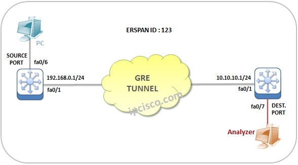
Table of Contents
Encapsulated Remote Switch Port Analyzer (ERSPAN) is another SPAN type that is used to mirror source ports/vlans traffic to destination ports over GRE Tunnels. Local SPAN is used to monitor the ports in the same switch, Remote SPAN is used to monitor ports in different swithces but use Layer 2 only. ERSPAN is used to monitor remote switch ports over Layer 3. This can be done over GRE Tunnels. Here, we will configure an ERSPAN example and learn ERSPAN Configuration on Cisco switches.
The topology for this Encapsulated Remote SPAN example will be like below:
Here, we will not configure a GRE Tunnel to focus only ERSPAN Config. We assume that there is a GRE tunnel between these switches. You can also check GRE Tunnel Configuration on Packet Tracer lesson.
For the first switch, Swithc 1, the source one, our ERSPAN Configuration Steps will be like below:
Now, let’s start our ERSPAN Configuration Example.
ERSPAN Source Interface Config
Fistly, we will configure ERSPAN Source interface. Our source port will be fastethernet 0/6 on switch 1. To do this, we will usethe below config:
Source-Switch-1# configure term
Source-Switch-1 (config)# monitor session 1 type erspan-source
Source-Switch-1 (config-mon-erspan-src)# source interface fa0/6
Source-Switch-1 (config-mon-erspan-src)# exit
ERSPAN-ID Config
To define the ERSPAN Destination, we will use “destination” keyword. Under it, we will configure ERSPAN ID. Here, our ERSPAN-ID will be, “123”.
Source-Switch-1 (config-mon-erspan-src)# destination
Source-Switch-1 (config-mon-erspan-src-dst)# erspan-id 123
Destination IP Config
After that, we will configure the IP address of the destination. This ip address is 10.10.10.1. This is the address of the GRE Tunnel destination.
Source-Switch-1 (config-mon-erspan-src-dst)# ip address 10.10.10.1
ERSPAN Source IP Config
Again under the destination, we will configure the ip address of the source device’s port. It will be 192.168.0.1. This is the address of the GRE tunnel source.
Source-Switch-1 (config-mon-erspan-src-dst)# origin ip address 192.168.0.1
Now, it is time to configure Switch 2, the destination switch. Here, we ill follow the below steps:
Now, let’s start our ERSPAN Configuration Example.
ERSPAN Destination Interface Config
In the second switch, we will configure the destination port. Our destination port will be 0/7. To do this, we will create ERSPAN process firstly.
Destination-Switch-2 (config)# monitor session 1 type erspan-destination
Destination-Switch-2 (config-mon-erspan-dst)# destination interface fa0/7
ERSPAN ID Config
To define the ERSPAN Source, we will use “source” keyword. Under it, we will configure ERSPAN ID. Here, our ERSPAN-ID will be, “123”.
Source-Switch-1 (config-mon-erspan-dst)# source
Source-Switch-1 (config-mon-erspan-dst-src)# erspan-id 123
ERSPAN Source IP Config
To define the ERSPAN Source IP, we will use the below command. Our source IP will be 10.10.10.1. This is the address of the GRE Tunnel destination.
Source-Switch-1 (config-mon-erspan-dst-src)# ip address 10.10.10.1
This is basically Cisco Encapsulated Remote SPAN Configuration with GRE tunnels.


Leave a Reply