- COURSES
- SPECIALS
- BLOG
- MEMBERS
- SHOP
- ABOUT
- ENROLL HERE
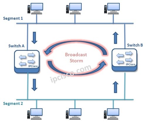
Table of Contents
Spanning Tree Protocol (STP) is a Layer 2 Loop Prevention protocol used in Ethernet networks. STP creates a loop-free topology by blocking redundant paths between switches while still allowing network redundancy. In this lesson, we will learn how STP works, why we need STP, STP types, BPDU messages, root bridge election, port states and basic Cisco STP configuration examples for CCNA studies.
In Layer 2 domain, redundancy is an important case. To provide redundant links, multiple connections are used between switches. But this redundancy mechanism can cause an undesirable situation that is called “L2 Loop”. To provide L2 redundancy and to avoid L2 loops, Spanning Tree Protocol (STP) was developed. In this lesson we will focus STP Overview. In another lesson we will focus STP Configuration. You can also view Spanning Tree Protocol details lesson.
During the development period, various versions of STP has been introduced. Different standards has been created beside Cisco specific versions. These STP versions are :
You can also view Cisco Packet Tracer Spanning Tree Spanning Tree Examples:
In this article, mainly we will focus on STP (802.1D).
Spanning Tree Protocol is one of the most used later 2 protocol in old and modern networks. Why do we need Spanning Tree Protocol. Here, we will focsu on the reasons of using STP.
Redundancy is an important term for a network. Layer 2 Redundancy is also important but need more caution. Without a mechanims like STP, Layer 2 Redundancy mechanisms can cause the below problems:
Let’s talk about each of these Layer 2 Redundacy problems.
Layer 2 Loops can occur when there is a multiple available Layer 2 link and this links also send and receive frames more than one. And because of the fact that, there is no TTL mechanims in Layer 2, Layer 2 Loops occurs. As you remember, in Layer 3, there is a TTL mechanism.
Think about the below topology:
Here, when Switch A receives a frame from Segment 1 and send it to the Segment 2, Switch B also can learn it from Segment 2. And it also sends this frame to Segment 1 as if it is being done first time. So, frames are doubled and a Layer 2 Loop Occured. And this Layer 2 loop causes a Broadcast Storm. An infinite frame send/receive process occurs.
One loop in a Layer 2 domain can cause one more Alyer 2 loops even if the siwtched network is a large network.
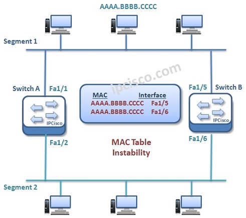
This Loops also cause a MAC Instability issue. As you remember, source address of a frame is important for MAC address types. These tables are created with source ports and MAC addresses. During a Loop, a frame can be received from different sources. So MAC Instability problem occurs. Here, a MAC table can have multiple MAC addresses for the same ports. This is an undefinable case for switches.
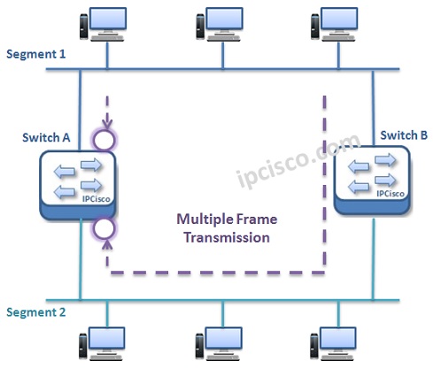
Multiple Frame Transmission is the problem of multiple, unnecessariliy transfer of Layer 2 frames. Because of there are multiple paths to a destination, same frame can be sent through different ways and this causes multiple frame transmission.
Spanning Tree Protocol (STP) has a mechanims to avoid Layer 2 Loops. With its mechanism, it checked all the available links. It determiens primary and backups of redundant links. According to some algorithms, some of the links pruned and only one available link become active at the same time to a destination. We can say that Spanning Tree Protocol (STP) mechanims basically prunes the unnecessary links at that time. If this link become offline because of a problem, then STP make another link as active. And the communication continue with another available way. At a time, only one link is active with STP. BPDU Messages are used in this operation.
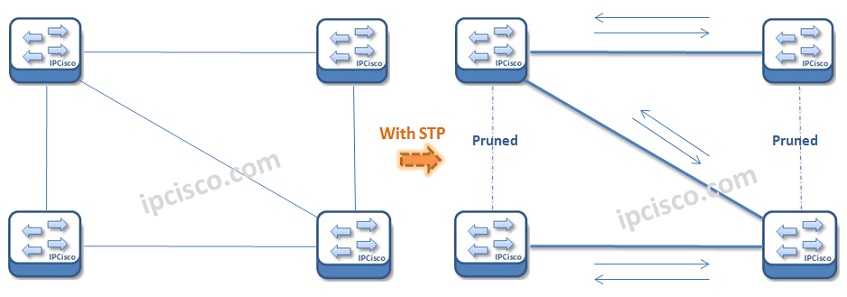
How STP Prunning Works?
BPDU is the abbreviation of Bridge Protocol Data Unit. BPDU messages are special STP frames exchanged between switches to share topology information. STP uses BPDUs to detect loops, elect the Root Bridge, calculate the best path to the Root Bridge, and monitor topology changes. Cisco switches send BPDU messages regularly to maintain a stable loop-free network topology. If a switch stops receiving BPDUs on a specific port, STP recalculates the topology and updates port states accordingly.
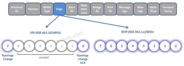
Bridge Protocol Data Unit (BPDU)
Spanning Tree Protocol (STP) elects one switch as the Root Bridge to create a loop-free Layer 2 topology. The Root Bridge becomes the central reference point for all path calculations in the network. STP selects the switch with the lowest Bridge ID as the Root Bridge. The Bridge ID consists of the switch priority value and MAC address. If two switches have the same priority, the switch with the lower MAC address wins the election process. In Cisco networks, administrators often manually configure the Root Bridge to optimize traffic flow and network stability.
Bridge ID = Switch Priority + MAC Address
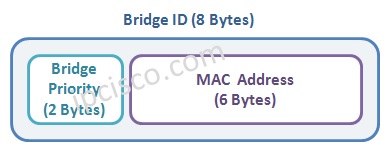
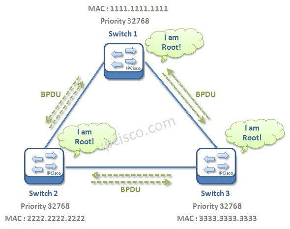
STP Root Bridge Election
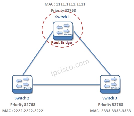
STP Root Bridge Election
STP assigns different port roles to prevent switching loops while maintaining network redundancy. These ports roles are given below:
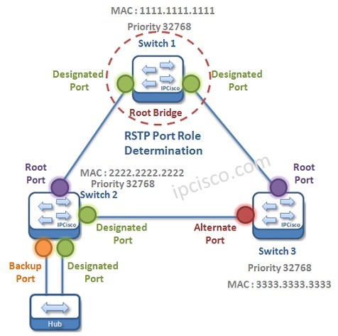
STP Port Roles
The Root Port is the port with the lowest path cost towards the Root Bridge.
Each network segment also has one Designated Port responsible for forwarding traffic to that segment.
Ports that could create Layer 2 loops become Non-Designated or Blocked Ports. These blocked ports do not forward user traffic but can become active if the primary path fails.
STP ports transition through different states before forwarding traffic. These states help prevent temporary loops during topology changes. these Port roles are given below:
In the Blocking state, a port only receives BPDU messages and does not forward frames.
In the Listening state, the switch processes BPDUs and prepares the topology.
In the Learning state, the switch learns MAC addresses but still does not forward user traffic.
Finally, in the Forwarding state, the port sends and receives normal traffic. STP may also place ports into the Disabled state if they are administratively shut down.


Leave a Reply