- COURSES
- SPECIALS
- BLOG
- MEMBERS
- SHOP
- ABOUT
- ENROLL HERE
Spanning Tree Protocol (STP) Operation is done with various sub processes. In this lesson, we will talk about each of these sub processes and explain STP Operation detailly. We will configure STP with Packet Tracer in another lesson.
Table of Contents
First of all STP gives some specific roles and names to the different switches in the switched domain. In STP world, bridge word is used instead of switch. So, the switches names will be according to these naming. What are these bridges?
There are two bridge types in STP:
Root Bridge is the main switch in STP domain. It is the central switch.
Non-Root Bridges are the other switches than Root Bridge. On each segment, one switch is selected as Designated Bridge and it handles all the communication from that LAN to Root Bridge.
Bridge ID is the identity of the switch. It is a 8 Bytes value that includes Bridge Priority and MAC Address. Bridge Priority is 2 Bytes and MAC address as you know 6 Bytes.
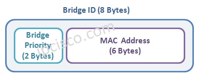
Bridge ID is very important during STP Operation. Acording to this value, Root Bridge is selected and become the central of switched network.
Rooot Bridge selection is done at the beginning of STP. It is done automatically by STP with Bridge ID values or we can manuplate Root Bridge Selection to select an optimim switch. The second way is always a good configuration habit. Because if a low capacity switch becomes a Root Bridge, then network can be affected badly.
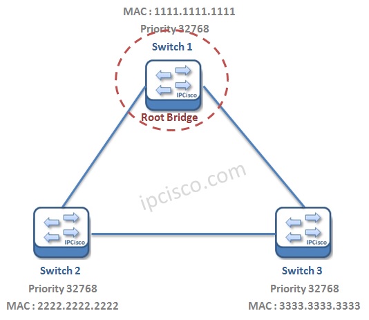
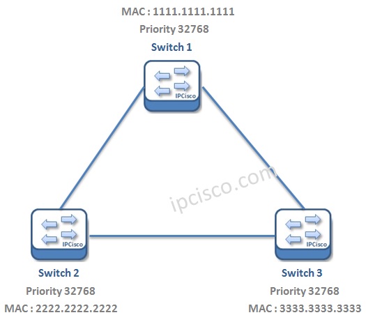
We can configure a specific switch as Root Bridge in some vendors. Another and more common way to do this is manuplating Bridge IDs. Bridge IDs consist of Bridge Priority and MAC address. We can not change MAC addresses, so we can do this by changing Bridge Priority values. The default priority is 32768. And setting the lowest priority on a switch, will provide this switch to be a Root Switch. The values of Bridge Priority increments by 4096.
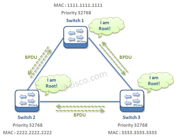
In Root Bridge Selection Process, all switches announce that the Root Bridge is itself with its Bridge ID values with BPDUs. Here, the switch that has the lowest Bridge ID, is selected as Root Bridge.
If the Root Bridge fails, other switches wait for a Max Age Time and then reconvergence period is started with a new Root Bridge Election.
Beside Switch Roles, Port Roles are also determined in Spanning Tree Protocol (STP) Operation. What are these Port Roles? STP Port Roles are:
Root Port is the port, that connects a switch to the Root Bridge with a lowest Cost.
Designated Port is the port, that connects the switch to a non-Root segment and can send the best BPDU on that segment.
Non Designated (Blocked) Port is the port, which is an other port than the Designated Port, in a segment.
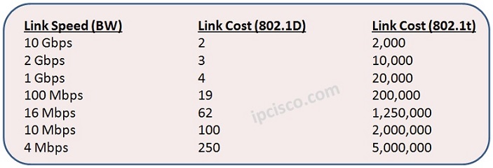
STP Port selection is done with the cost values. Some of the link speeds and their Cost are given below. According to different vendor’s, these cost can be a little different. For example a cost that is 2,000 in Cisco, can be 1,999 in Huawei. In Huawei switches, 802.1t standard is default.
The Port selection process is done orderly. First Root Bridge is selected, secondly Root Ports on all the switches, then Designated Ports are selected, and lastly the remainning ports become Non-Designated Port, meaning Blocking Port.
All switches in the switched domain has one Root Port that has a Lowest Cost to Root Bridge. The Root Ports are in “Forwarding State”.
The port of a switch that connects a switch to a Non-Root segment will be selected as Disagnated. This is done by selecting a Designated switch in that segment. The lowest cost switch to the Root Bridge is selected as Designated Switch. And its port in that segment is selected as Designated Port. The all port of the Root Bridge are also “Designated Ports”.
The other side of Designated Port is selected as Non Designated (Blocking) Port and Blocked.
Here, if a port become offline, then a Blocking Port become active and go into the Forwarding State.
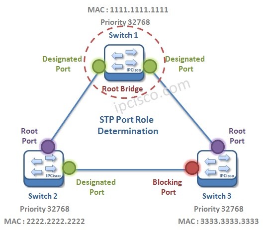
Think about the below topology. Let’s determine the STP Port Roles of this topology.
Here, after the Root Bridge Selection, port roles will be determined. The ports of the Root Bridge will be Designated Ports. The minimum Cost port from a switch to the Root Bridge will be selected as Root Ports. And on each segment there will be one Designated Port active and the oppusite direction of this port will be in Blocking.
In STP, different ports has different states to provide loop free Layer 2 Topology. What are these STP Port States? These are:
Disabled State is the state that means the port has not enabled yet. It also implies a failed port.
Listening State is the state, in which the root bridge and port roles are determined by sending and receiving BPDUs.
Learning State is the state that MAC Table is filled with the learned addresses.
Forwarding State is the state, that port has started to forwarding frames.
Blocking State is non transmitting state. This is the port that is selected as non-designated port. It can listens and forwards BPDUs, but can not forward frames.
When a failure occurs in an STP domain, a new paths become active. This causes a Topology Change. Without an inform, this can cause an instable MAC table. But to avoid this, STP provide a Topology Change Notification. This is also called TCN BPDU. TCN BPDU is sent as TC bit set and it updates the MAC Tables.
Think about the below topology. If the active port become down, how can STP handle this change?
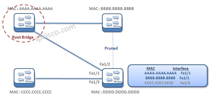
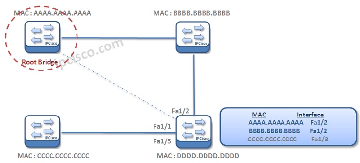
Here, TCN BPDUs are send to inform this situation. After that, the new path become available. This new active path is the previous blocked port.
![]()
As you can see, after the new port start to forward frames, the MAC table has also changed. By default the old value stays at the MAC table 300 seconds.
There is a Cisco specific feature used in Spanning Tree Protocol (STP). This feature is called “Portfast”. With Portfast, STP Learning and Listenning States can be bypassed and a port configured with Portfast can immediatelly go to the Forwarding State.
This Portfast feature is used for Host devices that has no drawback to pass into Forwarding State immediatelly.
There are different important timers in Spanning Tree Protocol (STP). These timers, their definions and the default values are given below:


Leave a Reply