- COURSES
- SPECIALS
- BLOG
- MEMBERS
- SHOP
- ABOUT
- ENROLL HERE
Theorically switches work in Layer 2 (Layer 2 switches). When you talk about switches, generally you do not think IP addresses. One of the ways that make a switch IP available is, configuring Switch Virtual Interfaces (SVI). Switch Virtual Interfaces (SVI) is basically, an IP assigned VLAN, an interface for that VLAN. Here, we will see SVI in Cisco, Cisco SVI Configuration.
You can DOWNLOAD the Cisco Packet Tracer example with .pkt format At the End of This Lessons.
You can also DOWNLOAD all the Packet Tracer examples with .pkt format in Packet Tracer Labs section.
Here, the important point is the switch type. If the switch is layer 2 switch, then you can configure one Switch Virtual Interface (SVI). But, in Multilayer switches, you can configure Switch Virtual Interfaces (SVI).
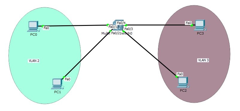
In this Switch Virtual Interfaces (SVI) Packet Tracer example, we will use a Multi Layer Switch and we will create two VLANs. In each VLAN, we will use 2 PCs. And in our Switch Virtual Interfaces (SVI) configuration, we will use two SVIs. After this configuration, Inter VLAN Routing will work and different VLANs can communicate.
")
Now, it is time to Switch Virtual Interface (SVI) configuration.
You can also check Packet Tracer Configuration Course For Cisco Hands on Experience
Let’s start with PC ip addresses. We will use the below IP addresses on these PCs. We will also configure the Gateway addresses of these PCs. The Gateway addresses are the addresses that we will configure as address of our Switch Virtual Interfaces (SVI).
PC0 : 10.0.0.2 255.255.255.0 GW: 10.0.0.1
PC1 : 10.0.0.3 255.255.255.0 GW: 10.0.0.1
PC2 : 20.0.0.2 255.255.255.0 GW: 20.0.0.1
PC3 : 20.0.0.3 255.255.255.0 GW: 20.0.0.1
On Muti Layer switch, we will create VLANs and we will assign the ports to these VLANs.
MLSwitch (config-vlan) # vlan 2
MLSwitch (config-vlan) # vlan 3
MLSwitch (config-vlan) # exit
MLSwitch (config) # interface range fastEthernet 0/1-2
MLSwitch (config-if-range) # switchport mode access
MLSwitch (config-if-range) # switchport access vlan 2
MLSwitch (config-if-range) # exit
MLSwitch (config) # interface range fastEthernet 0/3-4
MLSwitch (config-if-range) # switchport mode access
MLSwitch (config-if-range) # switchport access vlan 3
MLSwitch (config-if-range) # exit
VLAN configurations of our Switch Virtual Interface (SVI) topology is OK now.Let’s verify our VLANs.
MLSwitch # show vlan brief

VLAN Name Status Ports
---- -------------------------------- --------- -------------------------------
1 default active Fa0/5, Fa0/6, Fa0/7, Fa0/8
Fa0/9, Fa0/10, Fa0/11, Fa0/12
Fa0/13, Fa0/14, Fa0/15, Fa0/16
Fa0/17, Fa0/18, Fa0/19, Fa0/20
Fa0/21, Fa0/22, Fa0/23, Fa0/24
Gig0/1, Gig0/2
2 VLAN0002 active Fa0/1, Fa0/2
3 VLAN0003 active Fa0/3, Fa0/4
1002 fddi-default active
1003 token-ring-default active
1004 fddinet-default active
1005 trnet-default active
PC0 : 10.0.0.2 255.255.255.0
GW : 10.0.0.1
As you can see, our VLAN 2 and VLAN 3 are created and the ports are assigned to that VLANs.
It is time to configure our Switch Virtual Interfaces (SVI). Firstly we will enable “ip routing” on our Multi Layer Switch.
MLSwitch (config)# ip routing
Then, we will configure Switch Virtual Interfaces on MLSwitch.
MLSwitch (config)# interface VLAN 2
MLSwitch (config-if)# ip address 10.0.0.1 255.255.255.0
MLSwitch (config-if)# exit
MLSwitch (config)# interface VLAN 3
MLSwitch (config-if)# ip address 20.0.0.1 255.255.255.0
MLSwitch (config-if)# exit
Let’s verify Switch Virtual Interfaces (SVI) and the IP addresses assigned to this Switch Virtual Interfaces (SVI).
Switch# show ip interface brief
Interface IP-Address OK? Method Status Protocol

FastEthernet0/1 unassigned YES unset up up
FastEthernet0/2 unassigned YES unset up up
FastEthernet0/3 unassigned YES unset up up
FastEthernet0/4 unassigned YES unset up up
FastEthernet0/5 unassigned YES unset down down
FastEthernet0/6 unassigned YES unset down down
FastEthernet0/7 unassigned YES unset down down
FastEthernet0/8 unassigned YES unset down down
FastEthernet0/9 unassigned YES unset down down
FastEthernet0/10 unassigned YES unset down down
FastEthernet0/11 unassigned YES unset down down
FastEthernet0/12 unassigned YES unset down down
FastEthernet0/13 unassigned YES unset down down
FastEthernet0/14 unassigned YES unset down down
FastEthernet0/15 unassigned YES unset down down
FastEthernet0/16 unassigned YES unset down down
FastEthernet0/17 unassigned YES unset down down
FastEthernet0/18 unassigned YES unset down down
FastEthernet0/19 unassigned YES unset down down
FastEthernet0/20 unassigned YES unset down down
FastEthernet0/21 unassigned YES unset down down
FastEthernet0/22 unassigned YES unset down down
FastEthernet0/23 unassigned YES unset down down
FastEthernet0/24 unassigned YES unset down down
GigabitEthernet0/1 unassigned YES unset down down
GigabitEthernet0/2 unassigned YES unset down down
Vlan1 unassigned YES unset administratively down down
Vlan2 10.0.0.1 YES manual up up
Vlan3 20.0.0.1 YES manual up up
As you can see the IP addresses are assigned and the Switch Virtual Interfaces (SVI) are up.
Now, different PCs in different VLANs can communicate each other. To verify this, we will ping from one end in VLAN 2 to another end in VLAN 3. We will ping from PC0 to PC2.
PC0>ipconfig
FastEthernet0 Connection:(default port)
Link-local IPv6 Address.........: FE80::203:E4FF:FEA4:71C5
IP Address......................: 10.0.0.2
Subnet Mask.....................: 255.255.255.0
Default Gateway.................: 10.0.0.1
PC0>ping 20.0.0.3
Pinging 20.0.0.3 with 32 bytes of data:
Request timed out.
Reply from 20.0.0.3: bytes=32 time=0ms TTL=127
Reply from 20.0.0.3: bytes=32 time=0ms TTL=127
Reply from 20.0.0.3: bytes=32 time=0ms TTL=127
Ping statistics for 20.0.0.3:
Packets: Sent = 4, Received = 3, Lost = 1 (25% loss),
Approximate round trip times in milli-seconds:
Minimum = 0ms, Maximum = 0ms, Average = 0ms
As you can see, the ping is successful from one VLAN to another VLAN. Here, the pirst ping is lost because of ARP. This is another article’s lesson. If you ping again after first ping, you will successfull %100 of ping.
You can also DOWNLOAD all the Packet Tracer examples with .pkt format in Packet Tracer Labs section.
You can also check Packet Tracer Configuration Course For Cisco Hands on Experience


Leave a Reply