- COURSES
- SPECIALS
- BLOG
- MEMBERS
- SHOP
- BOOKSHELF
- ABOUT
- ENROLL HERE
In this MPLS lesson, we will focus on basic Cisco MPLS Configuration. We will study how to enable CEF, how to enable MPLS and how to configure label protocol ldp on Cisco routers. During this survey we will check the configuretion with various basic show command that will be useful during MPLS configurations.
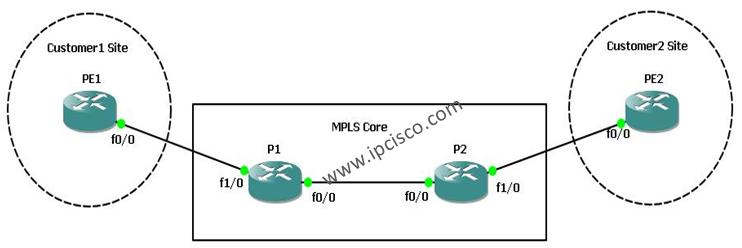
After successfully configuration of the core part, we will discuss hiding the core routes from the customer with disabling ttl propagate. For our Cisco MPLS Configuration Example, we will use the below topology:

Let’s start the configuration!
PE1 Router
PE1# configure terminalPE1(config)# ip cefPE1(config)# mpls label protocol ldpPE1(config)# interface fastethernet 0/0PE1(config-if)# mpls ipPE1(config-if)# end
PE2 Router
PE2# configure terminalPE2(config)# ip cefPE2(config)# mpls label protocol ldpPE2(config)# interface fastethernet 0/0PE2(config-if)# mpls ipPE2(config-if)# end
P1 Router
P1# configure terminalP1(config)# ip cefP1(config)# mpls label protocol ldpP1(config)# interface fastethernet 0/0P1(config-if)# mpls ipP1(config-if)# exitP1(config)# interface fastethernet 1/0P1(config-if)# mpls ipP1(config-if)# end
P2 Router
P2# configure terminalP2(config)# ip cefP2(config)# mpls label protocol ldpP2(config)# interface fastethernet 0/0P2(config-if)# mpls ipP2(config-if)# exitP2(config)# interface fastethernet 1/0P2(config-if)# mpls ipP2(config-if)# end
After the configuration of core routers(P1 and P2) and the customer edge routers(PE1 and PE2), it is time to verify our configuration.
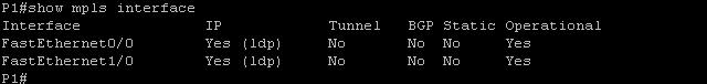
On router P1, use “show mpls interface” to verify that the interfaces are configured to use LDP.
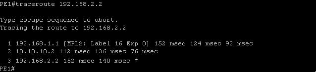
Without any configuration, customer side can see the core routers when they start a traceroute from one PE to another PE. Like below, the traceroute command show the core routers as hops.
PE1(config)# no tag-switching ip propagate-ttl
PE2(config)# no tag-switching ip propagate-ttl
P1(config)# no tag-switching ip propagate-ttl
P2(config)# no tag-switching ip propagate-ttl
After the configuration of this, core routers won’t seen by traceroute to the customers.
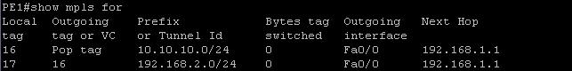
Lastly, on PE1 router, you can use the command to see the tags on this router.
We have finished basic Cisco MPLS Configuration example.
You can download the GNS3 configuration of this lab below.
Download Enabling MPLS Lab.


Leave a Reply