- COURSES
- SPECIALS
- BLOG
- MEMBERS
- SHOP
- BOOKSHELF
- ABOUT
- ENROLL HERE
Link Aggregation, LAG, Bundle, EtherChannel, what ever you say, they have the same logic in real. So, the configuration logic of Link Aggregation (LAG) is not different than Ether Channel logic on Cisco devices that run Cisco XR software. In this lesson,m we will learn How to configure Cisco IOS XR Link Aggregation, again the bundle is created and the ports are made to join to this bundle. And the same bundle members become like a single link together.
You can also check What is LACP and LACP Cisco Configuration on Cisco IOS lessons.
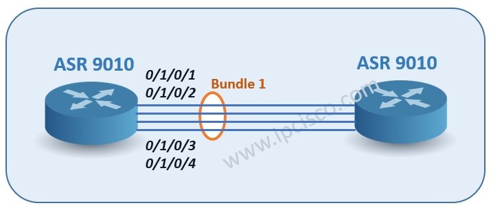
We will use the basic topology includes two ASR 9010 series like below.
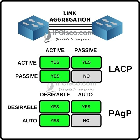
Let’s remember modes of link aggregation protocols, LACP and PAgP.
1. Firstly, let’s create a bundle on our router ASR 9010.
RP/0/RSP0/CPU0:asr9010_ipcisco(config)# # interface Bundle-Ether1
RP/0/RSP0/CPU0:asr9010_ipcisco(config-if)# description our_xr_bundle_istanbul_to_ankara
RP/0/RSP0/CPU0:asr9010_ipcisco(config-if)# mtu 9216
RP/0/RSP0/CPU0:asr9010_ipcisco(config-if)# bundle minimum-active links 3
RP/0/RSP0/CPU0:asr9010_ipcisco(config-if)# load interval 30
Here, our bundle type is Ethernet, because we want to aggregate Ethernet links. We are adding an optional description to our bundle and we are entering the mtu value. This mtu value can be given according to your companies values. We are configuring the minimum active links that means that if there are less links than this value, then bundle will be down. Lastly, we are adding load interval value as 30 seconds. This value is load calculation interval value.
2. Now, it is time to add intetfaces, under this Bundle.i
RP/0/RSP0/CPU0:asr9010_ipcisco(config)# interface TenGigE0/1/0/1
RP/0/RSP0/CPU0:asr9010_ipcisco(config-if)# description bundle_1_link_1
RP/0/RSP0/CPU0:asr9010_ipcisco(config-if)# bundle id 1 mode active
RP/0/RSP0/CPU0:asr9010_ipcisco(config-if)# load interval 30
RP/0/RSP0/CPU0:asr9010_ipcisco(config)# interface TenGigE0/1/0/2
RP/0/RSP0/CPU0:asr9010_ipcisco(config-if)# description bundle_2_link_1
RP/0/RSP0/CPU0:asr9010_ipcisco(config-if)# bundle id 1 mode active
RP/0/RSP0/CPU0:asr9010_ipcisco(config-if)# load interval 30
RP/0/RSP0/CPU0:asr9010_ipcisco(config-if)# exit
RP/0/RSP0/CPU0:asr9010_ipcisco(config)# interface TenGigE0/1/0/3
RP/0/RSP0/CPU0:asr9010_ipcisco(config-if)# description bundle_3_link_1
RP/0/RSP0/CPU0:asr9010_ipcisco(config-if)# bundle id 1 mode active
RP/0/RSP0/CPU0:asr9010_ipcisco(config-if)# load interval 30
RP/0/RSP0/CPU0:asr9010_ipcisco(config-if)# exit
RP/0/RSP0/CPU0:asr9010_ipcisco(config)# interface TenGigE0/1/0/4
RP/0/RSP0/CPU0:asr9010_ipcisco(config-if)# description bundle_4_link_1
RP/0/RSP0/CPU0:asr9010_ipcisco(config-if)# bundle id 1 mode active
RP/0/RSP0/CPU0:asr9010_ipcisco(config-if)# load interval 30
RP/0/RSP0/CPU0:asr9010_ipcisco(config-if)# exit
Under config mode, we are entering the interfaces that we would like to make the member of bundle. Then under each interface, we are adding an optional description, then we are entering the membership command (bundle id 1 mode active). Here, the active means, actively send LACP packets. And lastly,we are entering again load interval.
With this configuration, we have one bundle and 4 interfaces under this bundle. Remember, we have entered “bundle minimum-active links 3” command under bundle configuration. So, if one of this interfaces under bundle will down, our bundle will be still up and running. Because the remaining links under bundle will be 3. But, if two of these links become down, then our bundle will be down too. Because the minimum requirement for bundle will not satisfied.
3. Other end configuration.
Like above, we need to configure the other end. Because, as you know, bundle can be done with two ends. For both ends, the bundle and bundle member interface configurations must be done.
At the other end, the configurations can be the same, if you do not want to change your ports.
4. Verification.
After our bundle and interface configuration, we can verify our bundle configuration.
RP/0/RSP0/CPU0:asr9010_ipcisco # show bundle bundle-Ether 1
Bundle-Ether1
Status: Up
Local links <active/standby/configured>: 4/ 0 / 4
Local bandwidth <effective/available>: 80000000 (80000000) kbps
MAC address (source): 4055.396d.a523 (Chassis pool)
Inter-chassis link: No
Minimum active links / bandwidth: 7 / 1 kbps
Maximum active links: 64
Wait while timer: 2000 ms
Load balancing: Default
LACP: Operational
Flap suppression timer: Off
Cisco extensions: Disabled
Non-revertive: Disabled
mLACP: Not configured
IPv4 BFD: Not configuredPort Device State Port ID B/W, kbps
——————– ————— ———– ————– ———-
Te0/1/0/1 Local Active 0x8000, 0x001b 10000000
Link is Active
Te0/1/0/2 Local Active 0x8000, 0x001a 10000000
Link is Active
Te0/1/0/3 Local Active 0x8000, 0x0019 10000000
Link is Active
Te0/1/0/4 Local Active 0x8000, 0x0018 10000000
Link is Active
RP/0/RSP0/CPU0:asr9010_ipcisco # show bundle brief
Name | IG | State | LACP | BFD | Links | Local b/w, |
| | | | | act/stby/cfgd | kbps |
——-|———-|—————|——|—–|—————|————|
BE1 – Up On Off 0 / 0 / 4 0
…
…
You can also use “show bundle status” , “show bundle trace” and other detailed verification commands to verify your bundles.
RP/0/RSP0/CPU0:asr9010_ipcisco # show bundle ?
Bundle-Ether Aggregated Ethernet interface(s) | short name is BE
Bundle-POS Aggregated POS interface(s) | short name is BP
brief Display a brief output of all configured bundles
infrastructure Show infrastructure information for bundles and members.(cisco-support)
load-balancing Show load-balancing information for bundles and members.
platform-capability Show Platform Capability for bundles
protect Show protect information for bundles.
scheduled-actions Show scheduled actions for bundles
status Check the current status of the bundle subsystem
trace Show trace data for Bundle Manager(cisco-support)
| Output Modifiers
RP/0/RSP0/CPU0:asr9010_ipcisco # show bundle trace all ?
file Specific file(cisco-support)
hexdump Display traces in hexadecimal(cisco-support)
last Display last entries(cisco-support)
location Card location(cisco-support)
reverse Display latest traces first(cisco-support)
stats Display statistics(cisco-support)
tailf Display new traces as they are added(cisco-support)
unique Unique entries with counts(cisco-support)
usec Display timestamp w/usec detail(cisco-support)
verbose Display internal debugging information(cisco-support)
wide Dont display buffer name, node name, tid(cisco-support)
wrapping Wrapping entries(cisco-support)
| Output Modifiers


Leave a Reply