- COURSES
- SPECIALS
- BLOG
- MEMBERS
- SHOP
- BOOKSHELF
- ABOUT
- ENROLL HERE
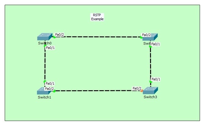
Table of Contents
As you know, STP (Spanning Tree Protocol) is the key protocol of Switching world. With STP, link redundancy is provided and switching loops are avoided. STP has different versions. One of the STP version is RSTP (Rapid Spanning Tree Protocol). Like its name, RSTP (Rapid Spanning Tree Protocol) is the fastest converged version of STP.
In this example, we will configure RSTP (Rapid Spanning Tree Protocol) with Packet Tracer.
You can DOWNLOAD the Cisco Packet Tracer example with .pkt format At the End of This Lesson.
For all Packet Tracer Examples and Files, you can check Packet Tracer Labs Page.
For our RSTP (Rapid Spanning Tree Protocol) example, we will use the below switching topology.

In STP (Spanning Tree Protocol), Blocking State is 20 seconds, Listenning State is 15 seconds and Learning State is 15 seconds. So, for STP, going through forwarding states needs 50 seconds. This total time is 15 seconds in RSTP (Rapid Spanning Tree Protocol). Because RSTP, bypasses the Blocking and Listenning states.
Let’s start to configure RSTP (Rapid Spanning Tree Protocol) on Cisco Packet Tracer.
Switch0(config)# spanning-tree mode ?
pvst Per-Vlan spanning tree mode
rapid-pvst Per-Vlan rapid spanning tree mode
Switch0 (config)# spanning-tree mode rapid-pvst
Switch0 (config)# end
Switch0 # copy running-config startup-config
Switch1 (config)# spanning-tree mode rapid-pvst
Switch1 (config)# end
Switch1 # copy running-config startup-config
For all Packet Tracer Examples and Files, you can check Packet Tracer Labs Page.
Switch2 (config)# spanning-tree mode rapid-pvst
Switch2 (config)# end
Switch2 # copy running-config startup-config
Switch3 (config)# spanning-tree mode rapid-pvst
Switch3 (config)# end
Switch3 # copy running-config startup-config
Now, let’s verify our RSTP (Rapid Spanning Tree Protocol) on Packet Tracer.
Switch0# show spanning-tree
VLAN0001 Spanning tree enabled protocol rstp
Root ID Priority 32769 Address 0006.2A11.24CC
This bridge is the root Hello Time 2 sec Max Age 20 sec
Forward Delay 15 sec Bridge ID Priority 32769 (priority 32768 sys-id-ext 1)
Address 0006.2A11.24CC Hello Time 2 sec Max Age 20 sec
Forward Delay 15 sec Aging Time 20 Interface Role Sts Cost Prio.Nbr Type
—————- —- — ——— ——– ——————————–
Fa0/1 Desg FWD 19 128.1 P2pFa0/2 Desg FWD 19 128.2 P2p
Here, Switch0 is the root bridge. The ports of Switch0 are both in Designated role and both of them is in Forwarding State.
Switch0# show spanning-tree summary
Switch is in rapid-pvst mode
Root bridge for: default
Extended system ID is enabled
Portfast Default is disabled
PortFast BPDU Guard Default is disabled
Portfast BPDU Filter Default is disabled
Loopguard Default is disabled
EtherChannel misconfig guard is disabled
UplinkFast is disabled
BackboneFast is disabled
Configured Pathcost method used is shortName Blocking Listening Learning Forwarding STP Active
———————- ——– ——— ——– ———- ———-
VLAN0001 0 0 0 2 2
———————- ——– ——— ——– ———- ———-
1 vlans 0 0 0 2 2
As you can see above, our mode is in rapid-pvst mode. And this is for one VLAN, VLAN 1.
We can also check the detailed RSTP (Rapid Spanning Tree Protocol) information with “show spanning-tree detail” command.
Switch0# show spanning-tree detail
VLAN0001 is executing the rstp compatible
Spanning Tree Protocol Bridge Identifier has priority of 32768, sysid 1, 0006.2A11.24CC
Configured hello time 2, max age 20, forward delay 15
Current root has priority 32769
Topology change flag not set, detected flag not set
Number of topology changes 0 last change occurred 00:00:00 ago from
FastEthernet0/1 Times: hold 1, topology change 35, notification 2 hello 2, max age 20, forward delay 15
Timers: hello 0, topology change 0, notification 0, aging 300
Port 1 (FastEthernet0/1) of VLAN0001 is designated forwarding
Port path cost 19, Port priority 128, Port Identifier 128.1
Designated bridge has priority 32769, address 0006.2A11.24CC
Designated port id is 128.1, designated path cost 19
Timers: message age 16, forward delay 0, hold 0 Number of transitions to forwarding state: 1
Link type is point-to-point by default Port 2 (FastEthernet0/2) of VLAN0001 is designated forwarding
Port path cost 19, Port priority 128, Port Identifier 128.2
Designated bridge has priority 32769, address 0006.2A11.24CC
Designated port id is 128.2, designated path cost 19 Timers: message age 16, forward delay 0, hold 0
Number of transitions to forwarding state: 1 Link type is point-to-point by default
Let’s check the show RSTP (Rapid Spanning Tree Protocol) on other switches.
Switch3# show spanning-tree
VLAN0001 Spanning tree enabled protocol rstp Root ID Priority 32769 Address 0006.2A11.24CC Cost 38 Port 1(FastEthernet0/1) Hello Time 2 sec Max Age 20 sec Forward Delay 15 sec Bridge ID Priority 32769 (priority 32768 sys-id-ext 1) Address 000A.4139.1675 Hello Time 2 sec Max Age 20 sec Forward Delay 15 sec
Aging Time 20Interface Role Sts Cost Prio.Nbr Type
—————- —- — ——— ——– ———
Fa0/1 Root FWD 19 128.1 P2p
Fa0/2 Altn BLK 19 128.2 P2pIn
Switch 3, one of the ports is in Forwarding State and the other is in Blocking State. The port role of Forwarding is “Root” role. The blocking port’s role is “Alternate”.
Switch2# show spanning-tree
VLAN0001 Spanning tree enabled protocol rstp Root ID Priority 32769 Address 0006.2A11.24CC Cost 19 Port 2(FastEthernet0/2) Hello Time 2 sec Max Age 20 sec Forward Delay 15 sec Bridge ID Priority 32769 (priority 32768 sys-id-ext 1) Address 0040.0B3D.0E38 Hello Time 2 sec Max Age 20 sec Forward Delay 15 sec
Aging Time 20
Interface Role Sts Cost Prio.Nbr Type
—————- —- — ——— ——– ———
Fa0/1 Desg FWD 19 128.1 P2p
Fa0/2 Root FWD 19 128.2 P2pIn
Switch2, the ports are both in Forwarding States and the roles are Designated and Root. As you remember, here, the Root port is the closest port to Root Bridge. It is same for Switch1 too.
Switch1# show spanning-tree
VLAN0001 Spanning tree enabled protocol rstp
Root ID Priority 32769 Address 0006.2A11.24CC
Cost 19 Port 1(FastEthernet0/1)
Hello Time 2 sec Max Age 20 sec
Forward Delay 15 sec
Bridge ID Priority 32769 (priority 32768 sys-id-ext 1)
Address 0060.4748.4B5A Hello Time 2 sec Max Age 20 sec
Forward Delay 15 sec Aging Time 20Interface Role Sts Cost Prio.Nbr Type
—————- —- — ——— ——– ———
Fa0/1 Root FWD 19 128.1 P2p
Fa0/2 Desg FWD 19 128.2 P2p
You can also test RSTP (Rapid Spanning Tree Protocol) states by deleting and then reconnecting the cables between switches. You will see that, the port states will rapidly go through Forwarding State.


Leave a Reply