- COURSES
- SPECIALS
- BLOG
- MEMBERS
- SHOP
- BOOKSHELF
- ABOUT
- ENROLL HERE
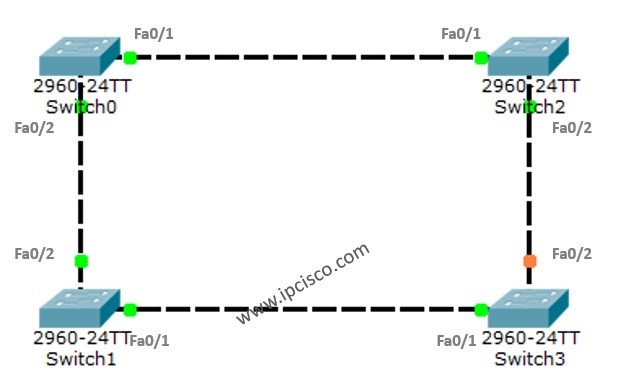
Table of Contents
In this post, instead of detaily talk about STP (Spanning Tree Protocol), we will focus on a basic Switching Loop topology and how STP mechanism helps to avoid this Switching Loop.
You can DOWNLOAD the Packet Tracer example with .pkt format HERE.
For all Packet Tracer Examples and Files, you can check Packet Tracer Labs Page.
Switching Loop is an unwanted problem in a network. Then, what is Switching Loop? Switching Loop is the situation, in which there are two layer 2 path between two layer 2 endpoint(switch, brigde). Switches creates broadcast storms from every port and switch rebroadcast again and again. Because of teh fact that there is no TTL (time to live) mechanism on layer 2, this continues forever.
To avoid this unwanted Switching Loops, there are some mechanisms. One of the most common name of this mechanisms is STP(Spanning Tree Protocol).
Acording to this protocol, in the switching topology, a Root Bridge is selected. And then the connected port of the switches are classified. The port classification and their meaning are like below:
The selection process is done orderly. First Root Bridge is selected, secondly Root Ports on all the switches, then Designated Ports are selected, and lastly the remainning ports become Non-Designated Port, meaning Blocking Port.
For STP example with PAcket Tracer, we will use the below switch topology.
 Example Topology on Packet Tracer")
On Switch0
Switch0#show spanning-tree
VLAN0001
Spanning tree enabled protocol ieee
Root ID Priority 32769
Address 0001.C90E.EDC0
This bridge is the root
Hello Time 2 sec Max Age 20 sec Forward Delay 15 secBridge ID Priority 32769 (priority 32768 sys-id-ext 1)
Address 0001.C90E.EDC0
Hello Time 2 sec Max Age 20 sec Forward Delay 15 sec
Aging Time 20Interface Role Sts Cost Prio.Nbr Type
—————- —- — ——— ——– ——————————–
Fa0/1 Desg FWD 19 128.1 P2p
Fa0/2 Desg FWD 19 128.2 P2p
Switch0#show spanning-tree active
VLAN0001
Spanning tree enabled protocol ieee
Root ID Priority 32769
Address 0001.C90E.EDC0
This bridge is the root
Hello Time 2 sec Max Age 20 sec Forward Delay 15 secBridge ID Priority 32769 (priority 32768 sys-id-ext 1)
Address 0001.C90E.EDC0
Hello Time 2 sec Max Age 20 sec Forward Delay 15 sec
Aging Time 20Interface Role Sts Cost Prio.Nbr Type
—————- —- — ——— ——– ——————————–
Fa0/1 Desg FWD 19 128.1 P2p
Fa0/2 Desg FWD 19 128.2 P2p
As we can see above, the addresses are for the Root and the Bridge part. So, Switch0 is selected as Root Bridge. The Root Bridge is selected according to the Bridge ID. The Bridge ID is the MAC address of the Switch. So, the lower one is selected as Root Bridge. This is Switch0.
The two port of Switch0 are normally Designated Port. Because all the ports on Root Bridge is always choosen as Designated Port.
Both of these ports are in Forwarding State, this means that they are ready to send the traffic. As a recall, as you know there are four states of an STP port. These are:
You can also use the following commands to check the spanning-tree information.
Switch0#show spanning-tree interface fa0/1
Vlan Role Sts Cost Prio.Nbr Type
—————- —- — ——— ——– ——————————–
VLAN0001 Desg FWD 19 128.1 P2p
For all Packet Tracer Examples and Files, you can check Packet Tracer Labs Page.
Switch0#show spanning-tree interface fa0/2
Vlan Role Sts Cost Prio.Nbr Type
—————- —- — ——— ——– ——————————–
VLAN0001 Desg FWD 19 128.2 P2pSwitch0#show spanning-tree vlan 1
VLAN0001
Spanning tree enabled protocol ieee
Root ID Priority 32769
Address 0001.C90E.EDC0
This bridge is the root
Hello Time 2 sec Max Age 20 sec Forward Delay 15 secBridge ID Priority 32769 (priority 32768 sys-id-ext 1)
Address 0001.C90E.EDC0
Hello Time 2 sec Max Age 20 sec Forward Delay 15 sec
Aging Time 20Interface Role Sts Cost Prio.Nbr Type
—————- —- — ——— ——– ——————————–
Fa0/1 Desg FWD 19 128.1 P2p
Fa0/2 Desg FWD 19 128.2 P2pYou can also use the below command for summary information:
Switch0#show spanning-tree summary
Switch is in pvst mode
Root bridge for: default
Extended system ID is enabled
Portfast Default is disabled
PortFast BPDU Guard Default is disabled
Portfast BPDU Filter Default is disabled
Loopguard Default is disabled
EtherChannel misconfig guard is disabled
UplinkFast is disabled
BackboneFast is disabled
Configured Pathcost method used is shortName Blocking Listening Learning Forwarding STP Active
———————- ——– ——— ——– ———- ———-
VLAN0001 0 0 0 2 2———————- ——– ——— ——– ———- ———-
1 vlans 0 0 0 2 2
For detailed information, use the below command:
Switch0#show spanning-tree detail
VLAN0001 is executing the ieee compatible Spanning Tree Protocol
Bridge Identifier has priority of 32768, sysid 1, 0001.C90E.EDC0
Configured hello time 2, max age 20, forward delay 15
Current root has priority 32769
Topology change flag not set, detected flag not set
Number of topology changes 0 last change occurred 00:00:00 ago
from FastEthernet0/1
Times: hold 1, topology change 35, notification 2
hello 2, max age 20, forward delay 15
Timers: hello 0, topology change 0, notification 0, aging 300Port 1 (FastEthernet0/1) of VLAN0001 is designated forwarding
Port path cost 19, Port priority 128, Port Identifier 128.1
Designated bridge has priority 32769, address 0001.C90E.EDC0
Designated port id is 128.1, designated path cost 19
Timers: message age 16, forward delay 0, hold 0
Number of transitions to forwarding state: 1
Link type is point-to-point by defaultPort 2 (FastEthernet0/2) of VLAN0001 is designated forwarding
Port path cost 19, Port priority 128, Port Identifier 128.2
Designated bridge has priority 32769, address 0001.C90E.EDC0
Designated port id is 128.2, designated path cost 19
Timers: message age 16, forward delay 0, hold 0
Number of transitions to forwarding state: 1
Link type is point-to-point by default
We checked the states on Root Bridge, Switch0. Now let’s check the other swicthes port states.
On Switch1
Switch1#show spanning-tree active
VLAN0001
Spanning tree enabled protocol ieee
Root ID Priority 32769
Address 0001.C90E.EDC0
Cost 19
Port 2(FastEthernet0/2)
Hello Time 2 sec Max Age 20 sec Forward Delay 15 secBridge ID Priority 32769 (priority 32768 sys-id-ext 1)
Address 0090.0CB7.18E5
Hello Time 2 sec Max Age 20 sec Forward Delay 15 sec
Aging Time 20Interface Role Sts Cost Prio.Nbr Type
—————- —- — ——— ——– ——————————–
Fa0/1 Desg FWD 19 128.1 P2p
Fa0/2 Root FWD 19 128.2 P2p
As you can see above, the root face of the switch, is the Root Port. Because all the cost are same, and it has a lower hop to the root. The other port is Designated Root.
On Switch2
Switch2#show spanning-tree active
VLAN0001
Spanning tree enabled protocol ieee
Root ID Priority 32769
Address 0001.C90E.EDC0
Cost 19
Port 1(FastEthernet0/1)
Hello Time 2 sec Max Age 20 sec Forward Delay 15 secBridge ID Priority 32769 (priority 32768 sys-id-ext 1)
Address 00D0.FF2E.5B1B
Hello Time 2 sec Max Age 20 sec Forward Delay 15 sec
Aging Time 20Interface Role Sts Cost Prio.Nbr Type
—————- —- — ——— ——– ——————————–
Fa0/2 Desg FWD 19 128.2 P2p
Fa0/1 Root FWD 19 128.1 P2p
On Switch3
Switch3#show spanning-tree active
VLAN0001
Spanning tree enabled protocol ieee
Root ID Priority 32769
Address 0001.C90E.EDC0
Cost 38
Port 1(FastEthernet0/1)
Hello Time 2 sec Max Age 20 sec Forward Delay 15 secBridge ID Priority 32769 (priority 32768 sys-id-ext 1)
Address 00D0.58E3.0126
Hello Time 2 sec Max Age 20 sec Forward Delay 15 sec
Aging Time 20Interface Role Sts Cost Prio.Nbr Type
—————- —- — ——— ——– ——————————–
Fa0/1 Root FWD 19 128.1 P2p
Fa0/2 Altn BLK 19 128.2 P2p
As you can see above, the STP blocks one of the port of Switch3. This election is done according to the cost to the root. The Designated Ports are selected and the remainning Non-Designated Port on a segment is blocked. Remember, only one Designated Port can exist in a segment.
We can summarize the last logical network topology like below:
 Example Topology on Packet Tracer")
I hope this can be useful for you, to understand STP better. STP(Spanning Tree Protocol) is the first protocol for this mechanism. Beside STP, there are many protocols used today. RSTP(Rapid Spanning Tree Protocol), PVRST (Per VLAN Rapid Spanning Tree), PVRST+ and MST are these protocol. In the following articles we will discuss these protocols one by one.
You can DOWNLOAD the Packet Tracer example with .pkt format HERE.
You can download “Packet Tracer” in Tools section.

Gokhan Kosem is a Network Engineer, Instructor and the Founder of IPCisco.com with 15+ years of experience in Cisco, Nokia, Huawei, Juniper, Linux, Service Provider Networks, Routing and Switching technologies.
He has worked on the backbone networks of major service providers and network vendors including Nortel, Alcatel-Lucent (Nokia) and has extensive hands-on experience with Cisco, Huawei, Juniper and Nokia networking technologies.
He has trained thousands of networking students worldwide through IPCisco.com, Udemy, books, labs, quizzes, and educational content across multiple social media platforms.
IPCisco.com | Best Route to Your Dreams


Leave a Reply