- COURSES
- SPECIALS
- BLOG
- MEMBERS
- SHOP
- BOOKSHELF
- ABOUT
- ENROLL HERE
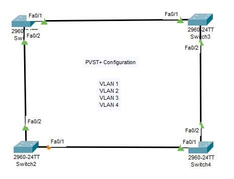
Table of Contents
In this Spanning Tree Configuration Example, we will configure STP with STP Mode PVST+. As you know, Per VLAN STP Plus is the STP Mode that uses one STP instances per VLAN.
For this Configuration Example, we will use the below switch topology.
We will do the below configuration steps for our PVST+ Configuration on Cisco Packet Tracer.
We will define VLAN 1,2,3 and for on each switch. VLAN 1 is also defined by default. SO it is not necessary to create it. The below configuration will be done on each switch.
Switch-1# configure terminal
Switch-1(config)# vlan 2
Switch-1(config-vlan)# vlan 3
Switch-1(config-vlan)# vlan 4
Switch-1(config-vlan)# exit
We will configure allt he interfaces between the switches as Trunk interfaces and we will set the allowed VLANs on these interfaces. Allowed VLANs are our VLANs that we have created before. We will do the same configuration on each switch.
Switch-1(config)# interface fastethernet 0/1
Switch-1(config-if)# switchport mode trunk
Switch-1(config-if)# switchport trunk allowed vlan 1-4
Switch-1(config-if)# exit
Switch-1(config)# interface fastethernet 0/2
Switch-1(config-if)# switchport mode trunk
Switch-1(config-if)# switchport trunk allowed vlan 1-4
We will set the stp mode as PVST on each switch.
Switch-1 (config)# spanning-tree mode ?
pvst Per-Vlan spanning tree mode
rapid-pvst Per-Vlan rapid spanning tree modeSwitch-1 (config)# spanning-tree mode pvst
After setting the STP Mode, the VLANs in the Per VLAN STP Domain will be defined on each switch like below.
Switch-1(config)# spanning-tree vlan 1-4
Switch-1(config)# exit
After the configuration, we will save the configuration on each switch.
Switch-1 # copy running-config startup-config
To verify our Per VLAN STP Plus configuration, we will use the below commands. You can find the outpıuts of some of them to learn PVST+ better.
Switch-1 # show spanning-tree summary
Switch is in pvst mode
Root bridge for:
Extended system ID is enabled
Portfast Default is disabled
PortFast BPDU Guard Default is disabled
Portfast BPDU Filter Default is disabled
Loopguard Default is disabled
EtherChannel misconfig guard is disabled
UplinkFast is disabled
BackboneFast is disabled
Configured Pathcost method used is shortName Blocking Listening Learning Forwarding STP Active
———————- ——– ——— ——– ———- ———-
VLAN0001 0 0 0 2 2
VLAN0002 0 0 0 2 2
VLAN0003 0 0 0 2 2
VLAN0004 0 0 0 2 2———————- ——– ——— ——– ———- ———-
4 vlans 0 0 0 8 8
Switch-1 # show spanning-tree
VLAN0001
Spanning tree enabled protocol ieee
Root ID Priority 32769
Address 0001.977C.4BD8
Cost 19
Port 1(FastEthernet0/1)
Hello Time 2 sec Max Age 20 sec Forward Delay 15 secBridge ID Priority 32769 (priority 32768 sys-id-ext 1)
Address 000D.BD4B.0AB2
Hello Time 2 sec Max Age 20 sec Forward Delay 15 sec
Aging Time 20Interface Role Sts Cost Prio.Nbr Type
—————- —- — ——— ——– ——————————–
Fa0/1 Root FWD 19 128.1 P2p
Fa0/2 Desg FWD 19 128.2 P2pVLAN0002
Spanning tree enabled protocol ieee
Root ID Priority 32770
Address 0001.977C.4BD8
Cost 19
Port 1(FastEthernet0/1)
Hello Time 2 sec Max Age 20 sec Forward Delay 15 secBridge ID Priority 32770 (priority 32768 sys-id-ext 2)
Address 000D.BD4B.0AB2
Hello Time 2 sec Max Age 20 sec Forward Delay 15 sec
Aging Time 20Interface Role Sts Cost Prio.Nbr Type
—————- —- — ——— ——– ——————————–
Fa0/1 Root FWD 19 128.1 P2p
Fa0/2 Desg FWD 19 128.2 P2pVLAN0003
Spanning tree enabled protocol ieee
Root ID Priority 32771
Address 0001.977C.4BD8
Cost 19
Port 1(FastEthernet0/1)
Hello Time 2 sec Max Age 20 sec Forward Delay 15 secBridge ID Priority 32771 (priority 32768 sys-id-ext 3)
Address 000D.BD4B.0AB2
Hello Time 2 sec Max Age 20 sec Forward Delay 15 sec
Aging Time 20Interface Role Sts Cost Prio.Nbr Type
—————- —- — ——— ——– ——————————–
Fa0/1 Root FWD 19 128.1 P2p
Fa0/2 Desg FWD 19 128.2 P2pVLAN0004
Spanning tree enabled protocol ieee
Root ID Priority 32772
Address 0001.977C.4BD8
Cost 19
Port 1(FastEthernet0/1)
Hello Time 2 sec Max Age 20 sec Forward Delay 15 secBridge ID Priority 32772 (priority 32768 sys-id-ext 4)
Address 000D.BD4B.0AB2
Hello Time 2 sec Max Age 20 sec Forward Delay 15 sec
Aging Time 20Interface Role Sts Cost Prio.Nbr Type
—————- —- — ——— ——– ——————————–
Fa0/1 Root FWD 19 128.1 P2p
Fa0/2 Desg FWD 19 128.2 P2p
Switch-1 # show spanning-tree vlan 1
VLAN0001
Spanning tree enabled protocol ieee
Root ID Priority 32769
Address 0001.977C.4BD8
Cost 19
Port 1(FastEthernet0/1)
Hello Time 2 sec Max Age 20 sec Forward Delay 15 secBridge ID Priority 32769 (priority 32768 sys-id-ext 1)
Address 000D.BD4B.0AB2
Hello Time 2 sec Max Age 20 sec Forward Delay 15 sec
Aging Time 20Interface Role Sts Cost Prio.Nbr Type
—————- —- — ——— ——– ——————————–
Fa0/1 Root FWD 19 128.1 P2p
Fa0/2 Desg FWD 19 128.2 P2p
Switch-1 # show spanning-tree vlan 2
VLAN0002
Spanning tree enabled protocol ieee
Root ID Priority 32770
Address 0001.977C.4BD8
Cost 19
Port 1(FastEthernet0/1)
Hello Time 2 sec Max Age 20 sec Forward Delay 15 secBridge ID Priority 32770 (priority 32768 sys-id-ext 2)
Address 000D.BD4B.0AB2
Hello Time 2 sec Max Age 20 sec Forward Delay 15 sec
Aging Time 20Interface Role Sts Cost Prio.Nbr Type
—————- —- — ——— ——– ——————————–
Fa0/1 Root FWD 19 128.1 P2p
Fa0/2 Desg FWD 19 128.2 P2p
Switch-2 # show spanning-tree vlan 1
VLAN0001
Spanning tree enabled protocol ieee
Root ID Priority 32769
Address 0001.977C.4BD8
Cost 38
Port 2(FastEthernet0/2)
Hello Time 2 sec Max Age 20 sec Forward Delay 15 secBridge ID Priority 32769 (priority 32768 sys-id-ext 1)
Address 0002.1737.C58D
Hello Time 2 sec Max Age 20 sec Forward Delay 15 sec
Aging Time 20Interface Role Sts Cost Prio.Nbr Type
—————- —- — ——— ——– ——————————–
Fa0/1 Altn BLK 19 128.1 P2p
Fa0/2 Root FWD 19 128.2 P2p
Switch-2 # show spanning-tree vlan 2
VLAN0002
Spanning tree enabled protocol ieee
Root ID Priority 32770
Address 0001.977C.4BD8
Cost 38
Port 2(FastEthernet0/2)
Hello Time 2 sec Max Age 20 sec Forward Delay 15 secBridge ID Priority 32770 (priority 32768 sys-id-ext 2)
Address 0002.1737.C58D
Hello Time 2 sec Max Age 20 sec Forward Delay 15 sec
Aging Time 20Interface Role Sts Cost Prio.Nbr Type
—————- —- — ——— ——– ——————————–
Fa0/1 Altn BLK 19 128.1 P2p
Fa0/2 Root FWD 19 128.2 P2p
Switch-2 # show spanning-tree vlan 3
VLAN0003
Spanning tree enabled protocol ieee
Root ID Priority 32771
Address 0001.977C.4BD8
Cost 38
Port 2(FastEthernet0/2)
Hello Time 2 sec Max Age 20 sec Forward Delay 15 secBridge ID Priority 32771 (priority 32768 sys-id-ext 3)
Address 0002.1737.C58D
Hello Time 2 sec Max Age 20 sec Forward Delay 15 sec
Aging Time 20Interface Role Sts Cost Prio.Nbr Type
—————- —- — ——— ——– ——————————–
Fa0/1 Altn BLK 19 128.1 P2p
Fa0/2 Root FWD 19 128.2 P2p
Switch-2# show spanning-tree vlan 4
VLAN0004
Spanning tree enabled protocol ieee
Root ID Priority 32772
Address 0001.977C.4BD8
Cost 38
Port 2(FastEthernet0/2)
Hello Time 2 sec Max Age 20 sec Forward Delay 15 secBridge ID Priority 32772 (priority 32768 sys-id-ext 4)
Address 0002.1737.C58D
Hello Time 2 sec Max Age 20 sec Forward Delay 15 sec
Aging Time 20Interface Role Sts Cost Prio.Nbr Type
—————- —- — ——— ——– ——————————–
Fa0/1 Altn BLK 19 128.1 P2p
Fa0/2 Root FWD 19 128.2 P2p
Switch-1 # show spanning-tree interface fastEthernet 0/1
Vlan Role Sts Cost Prio.Nbr Type
—————- —- — ——— ——– ——————————–
VLAN0001 Root FWD 19 128.1 P2p
VLAN0002 Root FWD 19 128.1 P2p
VLAN0003 Root FWD 19 128.1 P2p
VLAN0004 Root FWD 19 128.1 P2p
Switch-1 # show spanning-tree interface fastEthernet 0/2
Vlan Role Sts Cost Prio.Nbr Type
—————- —- — ——— ——– ——————————–
VLAN0001 Desg FWD 19 128.2 P2p
VLAN0002 Desg FWD 19 128.2 P2p
VLAN0003 Desg FWD 19 128.2 P2p
VLAN0004 Desg FWD 19 128.2 P2p
Switch-2 # show spanning-tree interface fastEthernet 0/1
Vlan Role Sts Cost Prio.Nbr Type
—————- —- — ——— ——– ——————————–
VLAN0001 Altn BLK 19 128.1 P2p
VLAN0002 Altn BLK 19 128.1 P2p
VLAN0003 Altn BLK 19 128.1 P2p
VLAN0004 Altn BLK 19 128.1 P2p
Switch-2 # show spanning-tree interface fastEthernet 0/2
Vlan Role Sts Cost Prio.Nbr Type
—————- —- — ——— ——– ——————————–
VLAN0001 Root FWD 19 128.2 P2p
VLAN0002 Root FWD 19 128.2 P2p
VLAN0003 Root FWD 19 128.2 P2p
VLAN0004 Root FWD 19 128.2 P2p
Switch-4 # show spanning-tree interface fastEthernet 0/1
Vlan Role Sts Cost Prio.Nbr Type
—————- —- — ——— ——– ——————————–
VLAN0001 Desg FWD 19 128.1 P2p
VLAN0002 Desg FWD 19 128.1 P2p
VLAN0003 Desg FWD 19 128.1 P2p
VLAN0004 Desg FWD 19 128.1 P2p
Switch-4 # show spanning-tree interface fastEthernet 0/2
Vlan Role Sts Cost Prio.Nbr Type
—————- —- — ——— ——– ——————————–
VLAN0001 Root FWD 19 128.2 P2p
VLAN0002 Root FWD 19 128.2 P2p
VLAN0003 Root FWD 19 128.2 P2p
VLAN0004 Root FWD 19 128.2 P2p
Switch-1 # show spanning-tree detail
VLAN0001 is executing the ieee compatible Spanning Tree Protocol
Bridge Identifier has priority of 32768, sysid 1, 000D.BD4B.0AB2
Configured hello time 2, max age 20, forward delay 15
Current root has priority 32769
Root port is 1 (FastEthernet0/1), cost of root path is 19
Topology change flag not set, detected flag not set
Number of topology changes 0 last change occurred 00:00:00 ago
from FastEthernet0/1
Times: hold 1, topology change 35, notification 2
hello 2, max age 20, forward delay 15
Timers: hello 0, topology change 0, notification 0, aging 300Port 1 (FastEthernet0/1) of VLAN0001 is root forwarding
Port path cost 19, Port priority 128, Port Identifier 128.1
Designated root has priority 32769, address 0001.977C.4BD8
Designated bridge has priority 32769, address 0001.977C.4BD8
Timers: message age 16, forward delay 0, hold 0
Number of transitions to forwarding state: 1
Link type is point-to-point by defaultPort 2 (FastEthernet0/2) of VLAN0001 is designated forwarding
Port path cost 19, Port priority 128, Port Identifier 128.2
Designated root has priority 32769, address 0001.977C.4BD8
Designated bridge has priority 32769, address 000D.BD4B.0AB2
Designated port id is 128.2, designated path cost 19
Timers: message age 16, forward delay 0, hold 0
Number of transitions to forwarding state: 1
Link type is point-to-point by defaultVLAN0002 is executing the ieee compatible Spanning Tree Protocol
Bridge Identifier has priority of 32768, sysid 2, 000D.BD4B.0AB2
Configured hello time 2, max age 20, forward delay 15
Current root has priority 32770
Root port is 1 (FastEthernet0/1), cost of root path is 19
Topology change flag not set, detected flag not set
Number of topology changes 0 last change occurred 00:00:00 ago
from FastEthernet0/1
Times: hold 1, topology change 35, notification 2
hello 2, max age 20, forward delay 15
Timers: hello 0, topology change 0, notification 0, aging 300Port 1 (FastEthernet0/1) of VLAN0002 is root forwarding
Port path cost 19, Port priority 128, Port Identifier 128.1
Designated root has priority 32770, address 0001.977C.4BD8
Designated bridge has priority 32770, address 0001.977C.4BD8
Timers: message age 16, forward delay 0, hold 0
Number of transitions to forwarding state: 1
Link type is point-to-point by defaultPort 2 (FastEthernet0/2) of VLAN0002 is designated forwarding
Port path cost 19, Port priority 128, Port Identifier 128.2
Designated root has priority 32770, address 0001.977C.4BD8
Designated bridge has priority 32770, address 000D.BD4B.0AB2
Designated port id is 128.2, designated path cost 19
Timers: message age 16, forward delay 0, hold 0
Number of transitions to forwarding state: 1
Link type is point-to-point by defaultVLAN0003 is executing the ieee compatible Spanning Tree Protocol
Bridge Identifier has priority of 32768, sysid 3, 000D.BD4B.0AB2
Configured hello time 2, max age 20, forward delay 15
Current root has priority 32771
Root port is 1 (FastEthernet0/1), cost of root path is 19
Topology change flag not set, detected flag not set
Number of topology changes 0 last change occurred 00:00:00 ago
from FastEthernet0/1
Times: hold 1, topology change 35, notification 2
hello 2, max age 20, forward delay 15
Timers: hello 0, topology change 0, notification 0, aging 300Port 1 (FastEthernet0/1) of VLAN0003 is root forwarding
Port path cost 19, Port priority 128, Port Identifier 128.1
Designated root has priority 32771, address 0001.977C.4BD8
Designated bridge has priority 32771, address 0001.977C.4BD8
Timers: message age 16, forward delay 0, hold 0
Number of transitions to forwarding state: 1
Link type is point-to-point by defaultPort 2 (FastEthernet0/2) of VLAN0003 is designated forwarding
Port path cost 19, Port priority 128, Port Identifier 128.2
Designated root has priority 32771, address 0001.977C.4BD8
Designated bridge has priority 32771, address 000D.BD4B.0AB2
Designated port id is 128.2, designated path cost 19
Timers: message age 16, forward delay 0, hold 0
Number of transitions to forwarding state: 1
Link type is point-to-point by defaultVLAN0004 is executing the ieee compatible Spanning Tree Protocol
Bridge Identifier has priority of 32768, sysid 4, 000D.BD4B.0AB2
Configured hello time 2, max age 20, forward delay 15
Current root has priority 32772
Root port is 1 (FastEthernet0/1), cost of root path is 19
Topology change flag not set, detected flag not set
Number of topology changes 0 last change occurred 00:00:00 ago
from FastEthernet0/1
Times: hold 1, topology change 35, notification 2
hello 2, max age 20, forward delay 15
Timers: hello 0, topology change 0, notification 0, aging 300Port 1 (FastEthernet0/1) of VLAN0004 is root forwarding
Port path cost 19, Port priority 128, Port Identifier 128.1
Designated root has priority 32772, address 0001.977C.4BD8
Designated bridge has priority 32772, address 0001.977C.4BD8
Timers: message age 16, forward delay 0, hold 0
Number of transitions to forwarding state: 1
Link type is point-to-point by defaultPort 2 (FastEthernet0/2) of VLAN0004 is designated forwarding
Port path cost 19, Port priority 128, Port Identifier 128.2
Designated root has priority 32772, address 0001.977C.4BD8
Designated bridge has priority 32772, address 000D.BD4B.0AB2
Designated port id is 128.2, designated path cost 19
Timers: message age 16, forward delay 0, hold 0
Number of transitions to forwarding state: 1
Link type is point-to-point by default
After our PVST+ configuration on Packet Tracer, I will show you some manuplation commands on Cisco switches. Some of the important of these commands are explained one by one below:
The default Bridge Priotiy value is 32768. The priority value can be anything between 0 and 61440 but must be multiples of 4096. (0, 4096, 8192, 12288 etc.)
Switch-1(config)# spanning-tree vlan 1 priority 4096
Switch-2 (config)# spanning-tree vlan 1 priority 8192
Switch-3(config)# spanning-tree vlan 1 priority 8192
Switch-4 (config)# spanning-tree vlan 1 priority 12288
According to above configuration, Switch 1 will be elected as Root Bridge for VLAN 1.
Or for the below configuration, Switch 2 will be elected as Root Bridge for VLAN 4.
Switch-1(config)# spanning-tree vlan 4 priority 12288
Switch-2 (config)# spanning-tree vlan 4 priority 8192
Switch-3(config)# spanning-tree vlan 4 priority 16384
Switch-4 (config)# spanning-tree vlan 4 priority 12288
This priority is configured for each VLAN on each switch. according to these values, the switch with the lowest Bridge ID will be elected as Root Bridge. So, the lowest Priority will effect this election. (Bridge ID = Bridge Priority + MAC)
This Root Bridge election can be done also via “root primary” keyword for each VLAN on each switch. For example, with the below configuration, switch 1 will be the Root Pridge for VLAN 1, Swith 2 will be Root Bridge for VLAN 3 and so on.
Switch-1(config)# spanning-tree vlan 1 root primary
Switch-2(config)# spanning-tree vlan 3 root primary
Switch-3(config)# spanning-tree vlan 4 root primary
Switch-4(config)# spanning-tree vlan 2 root primary
Beside, port priorities can be set like normal STP. But here, for each VLAN, a specific port priority can be given.
Switch-1(config)# spanning-tree port-priority 150
Spanning Tree timers are the other configuration parameters for PVST+. We can set the some of the timers as below:
Switch-1(config)# spanning-tree vlan 3 hello-time 5
Switch-1(config)# spanning-tree vlan 2 forward-time 13
Switch-1(config)# spanning-tree vlan 4 max-age 24
To restart PVST+, we will use “clear spanning-tree detected protocol” command. We can also use this protocol for specific interfaces.
Switch-1(config)# clear spanning-tree detected-protocol [interface interface]
After PVST+ configuration, we can verify our configuration with “show spanning-tree” command.
Switch-1 # show spanning-tree
To configure Rapid PVST+ on Cisco switches we should follow the similar steps like PVST+ Configuration. But here, the STP Mode selection is different as you know.
We will configure the below mode change on each switch in the STP Domain.
Switch-1(config)# spanning-tree mode ?
pvst Per-Vlan spanning tree mode
rapid-pvst Per-Vlan rapid spanning tree mode
Switch-1(config)# spanning-tree mode rapid-pvst


Leave a Reply