- COURSES
- SPECIALS
- BLOG
- MEMBERS
- SHOP
- ABOUT
- ENROLL HERE
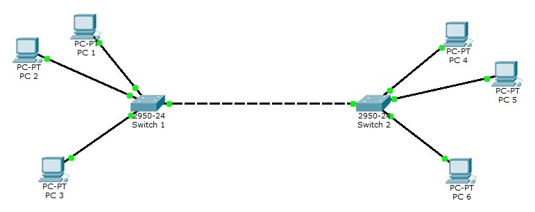
Table of Contents
As an example, you can see a VLAN topology below. In this topology, 2 Cisco Catalyst 2950-24 switches and 6 PCs are used.

For all Packet Tracer Examples and Files, you can check Packet Tracer Labs Page.
For our VLAN Configuration example, we will set our PC IPaddresses as below. These ip addresses will be required at the end of this configuration example to test our configuration.
PC 1 –> 192.168.1.2 VLAN 2
PC 2 –> 192.168.1.3 VLAN 2
PC 3 –> 192.168.1.4 VLAN 3
PC 4 –> 192.168.1.6 VLAN 3
PC 5 –> 192.168.1.7 VLAN 3
PC 6 –> 192.168.1.8 VLAN 2
After PC IP configurations, now, we can start our VLAN Packet Tracer Configuration steps. Here, we will follow the below steps:
Switch 1(config)# interface fastEthernet 0/2
Switch 1(config-if)# switchport mode access
Switch 1(config-if)# switchport access vlan 2
Switch 1(config)# interface fastEthernet 0/3
Switch 1(config-if)# switchport mode access
Switch 1(config-if)# switchport access vlan 2
Switch 1(config)# interface fastEthernet 0/4
Switch 1(config-if)# switchport mode access
Switch 1(config-if)# switchport access vlan 3
Switch 1(config)# interface fastEthernet 0/1
Switch 1(config-if)# switchport mode trunk
Switch 1(config-if)# switchport nonegotiate
Switch 1(config-if)# switchport trunk allowed vlan 2-4
Switch 1# copy running-config startup-config
After configuring the first switch, we will configure switch 2 similar to switch 1 as below.
Switch 2(config)# interface fastEthernet 0/2
Switch 2(config-if)# switchport mode access
Switch 2(config-if)# switchport access vlan 3
Switch 2(config)# interface fastEthernet 0/3
Switch 2(config-if)# switchport mode access
Switch 2(config-if)# switchport access vlan 2
Switch 2(config)# interface fastEthernet 0/4
Switch 2(config-if)# switchport mode access
Switch 2(config-if)# switchport access vlan 2
Switch 2(config)# interface fastEthernet 0/1
Switch 2(config-if)# switchport mode trunk
Switch 2(config-if)# switchport nonegotiate
Switch 2(config-if)# switchport trunk allowed vlan 2-4
Switch 2# copy running-config startup-config
Our last step of VLAN Packet Tracer Example is configuration verification. to verify our VLAN Packet Tracer Configuration, we will use verification commands like “show vlan brief“, “show interfaces“, “show interfaces trunk” etc.
Switch# show vlan brief
VLAN Name Status Ports
—- ——————————– ——— ——————————-
1 default active Fa0/5, Fa0/6, Fa0/7, Fa0/8 Fa0/9,
Fa0/10, Fa0/11, Fa0/12 Fa0/13, Fa0/14,
Fa0/15, Fa0/16 Fa0/17, Fa0/18, Fa0/19,
Fa0/20 Fa0/21, Fa0/22, Fa0/23, Fa0/24
2 VLAN0002 active Fa0/2, Fa0/3
3 VLAN0003 active Fa0/4
1002 fddi-default active
1003 token-ring-default active
1004 fddinet-default active
1005 trnet-default active
For all Packet Tracer Examples and Files, you can check Packet Tracer Labs Page.


Leave a Reply