In this lesson we will concentrate on OSPF Standard Area and OSPF Backbone Area. We will do a Multi Area OSPF Configuration With Backbone Area and OSPF Standard Areas. In other lesson, we will also give example for the other OSPF Area Types and their configuration examples on Packet Tracer.
You can DOWNLOAD the Cisco Packet Tracer example with .pkt format at the end of this lesson.
As you know from the previous lessons, OSPF has 6 different areas. These areas are:
Backbone Area
Standard (Normal) Area
Stub Area
Totally-Stub Area
Not-So-Stubby Area (NSSA)
Totally Not-So-Stubby Area
You can check the below lessons for the configuration of different OSPF Area Types:
In this first post, we will focus on Backbone Area and Standard (Normal) Area. Beside this, we will see the configuration of virtual-link on OSPF. What was the virtual-link? It was the link that used to connect the normal areas to the backbone area, if they are not connected directly to the backbone area. Remember, in OSPF, there was a rule. All areas must be connected to the backbone area, Area 0. If they are not, they can temporarily connect to the backbone via virtual-links.
OSPF Backbone Area and Standard Area with Accepted LSAs
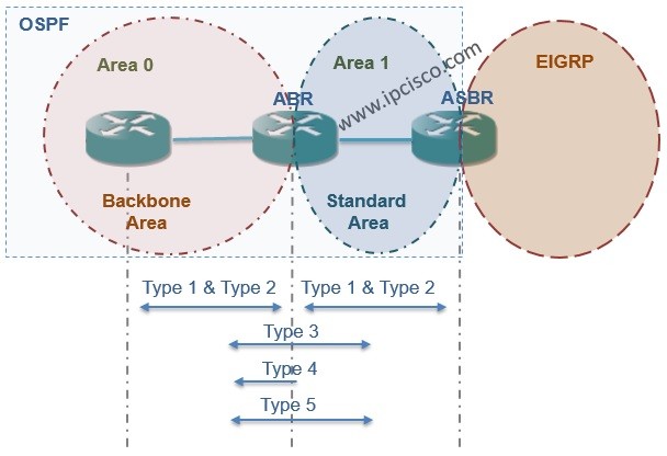
Backbone Area is also a Normal Area but it is Area 0.
Normal Areas accept the Summary LSAs from other Areas (Type 3 and Type 4 LSAs). They accept also the External LSAs (Type 5 LSAs). Type 1 and Type 2 LSA are already accepted inside area.
We talked about theorical too much. This post aims to show you the configuration of this areas and as you know, doing the configuration is the most effective way of learning network protocols.
Our topology will be like below fort he first example.
OSPF Backbone Area, Standard Area and
Virtual-Link Example Topology
As you can see, in this topology, there are Backbone Area (Area 0) and three standard (normal) areas (Area 1, Area 2, Area3).
Firstly let’s configure the IP Addresses on all routers:
Router1
Router1>enable
Router1# configure terminal
Router1(config)# interface GigabitEthernet0/0
Router1(config-if)# ip address 10.1.0.1 255.255.255.0
Router1(config-if)# no shutdown
Router1(config-if)# exit
Router1(config)# interface GigabitEthernet0/1
Router1(config-if)# ip address 10.2.0.1 255.255.255.0
Router1(config-if)# no shutdown
Router1(config-if)# end
Router1# copy running-config startup-config
Router2
Router2>enable
Router2# configure terminal
Router2(config)# interface GigabitEthernet0/0
Router2(config-if)# ip address 10.1.0.2 255.255.255.0
Router2(config-if)# no shutdown
Router2(config-if)# exit
Router2(config)# interface GigabitEthernet0/1
Router2(config-if)# ip address 10.3.0.1 255.255.255.0
Router2(config-if)# no shutdown
Router2(config-if)# end
Router2# copy running-config startup-config
Router4>enable
Router4# configure terminal
Router4(config)# interface GigabitEthernet0/0
Router4(config-if)# ip address 10.4.0.1 255.255.255.0
Router4(config-if)# no shutdown
Router4(config-if)# exit
Router4(config)# interface GigabitEthernet0/1
Router4(config-if)# ip address 10.3.0.2 255.255.255.0
Router4(config-if)# no shutdown
Router4(config-if)# end
Router4# copy running-config startup-config
Router5
Router5>enable
Router5# configure terminal
Router5(config)# interface GigabitEthernet0/0
Router5(config-if)# ip address 10.4.0.2 255.255.255.0
Router5(config-if)# no shutdown
Router5(config-if)# exit
Router5(config)# interface GigabitEthernet0/1
Router5(config-if)# ip address 10.5.0.1 255.255.255.0
Router5(config-if)# no shutdown
Router5(config-if)# end
Router5# copy running-config startup-config
Router6
Router6>enable
Router6# configure terminal
Router6(config)# interface GigabitEthernet0/1
Router6(config-if)# ip address 10.5.0.2 255.255.255.0
Router6(config-if)# no shutdown
Router6(config-if)# end
Router6# copy running-config startup-config
After this basic interface configurations, let’s configure the OSPF on all routers. Here, OSPF process number will be 1 and the Routerx’s router ID will be x.x.x.x. Beside this, all the connected areas will be configured.
Router1
Router1>enable
Router1# configure terminal
Router1(config)# router ospf 1
Router1(config-router)# router-id 1.1.1.1
Router1(config-router)# network 10.1.0.0 0.0.0.255 area 0
Router1(config-router)# network 10.2.0.0 0.0.0.255 area 1
Router1(config-router)# end
Router1# copy running-config startup-config
Router2
Router2>enable
Router2# configure terminal
Router2(config)# router ospf 1
Router2(config-router)# router-id 2.2.2.2
Router2(config-router)# network 10.1.0.0 0.0.0.255 area 0
Router2(config-router)# network 10.3.0.0 0.0.0.255 area 2
Router2(config-router)# end
Router2# copy running-config startup-config
After doing this configuration we will see all the network on Topology Table except Area 3. Area 3 is not directly connected to the Backbone Area,Area 0. So in the routing table of the routers there will be no route to this Area 3.


Leave a Reply