- COURSES
- SPECIALS
- BLOG
- MEMBERS
- SHOP
- BOOKSHELF
- ABOUT
- ENROLL HERE
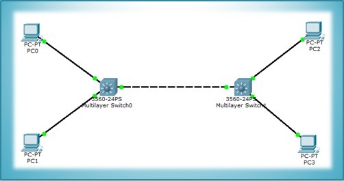
Table of Contents
In this article, we will focus on how to configure VTP, with Packet Tracer. For VTP Configuration, we will use the topology below with two switches and two PCs.

You can DOWNLOAD the Packet Tracer example with .pkt format HERE.
For all Packet Tracer Examples and Files, you can check Packet Tracer Labs Page.
First of all we should configure the trunk between swithes. Because VTP information pass through only on trunk links on management VLAN (VLAN 1). To do this:
SwitchA> enableSwitchA# configure terminalSwitchA(config)# interface fa 0/24SwitchA(config-if)#switchport trunk encapsulation dot1qSwitchA(config-if)# switchport mode trunk%LINEPROTO-5-UPDOWN: Line protocol on Interface FastEthernet0/24, changed state to down%LINEPROTO-5-UPDOWN: Line protocol on Interface FastEthernet0/24, changed state to upSwitchA(config-if)# end
Now the trunk is activated. For switchport mode trunk command it is not necessary to use the same command at the other side of the link, without this job it is automatically activated.
In this steo, we will configure Switch A as a VTP Server and the Switch B as a VTP Client. The default switch VTP mode is VTP Server, so we will not change anything on SwitchA. But in SwitchB we will change vtp mode. Then in both switches we will configure VTP domain, VTP password, vtp version and vtp prunning.
Firstly, let’s start with switch B and set switch B as vtp client mode.
SwitchB> enable
SwitchB# configure terminalSwitchB(config)# vtp mode client
SwitchB(config)# vtp domain cisco
SwitchB(config)# vtp password abc123SwitchB(config)# vtp version 2SwitchB(config)# vtp prunning enableSwitchB(config)# end
Now, it is time to configure switch A. We will configure the same parameters for the Switch A except VTP Mode. Switch A will be in VTP Server Mode by default. But to show you, we will use “vtp server mode” command..
SwitchA# enable
SwitchA(config)# vtp mode server
SwitchA(config)# vtp domain ciscooChanging VTP domain name from NULL to ciscoo04:50:49 %DTP-5-DOMAINMISMATCH: Unable to perform trunk negotiationon port Fa0/24 because of VTP domain mismatch.
SwitchA(config)# vtp domain cisco
SwitchA(config)# vtp password abc123SwitchA(config)# vtp version 2SwitchA(config)# vtp prunning enable
SwitchA(config)# end
Here, during VTP domain configuration, an error occurred because of the domain missmatch and after that when we corrected the configuration then this error dissappeared.
To verify Cisco VTP Configuration, we will use “show vtp status” command on both switches.
SwithA# show vtp status
VTP Version : 2
Configuration Revision : 0
Maximum VLANs supported locally : 255
Number of existing VLANs : 5
VTP Operating Mode : Server
VTP Domain Name : cisco
VTP Pruning Mode : Disabled
VTP V2 Mode : Disabled
VTP Traps Generation : Disabled
MD5 digest : 0x12 0x34 0xBB 0x77 0x23 0xa4 0xA6 0x86
Configuration last modified by 0.0.0.0 at 4-6-23 07:15:24
Local updater ID is 0.0.0.0 (no valid interface found)
SwithB# show vtp status
VTP Version : 2
Configuration Revision : 0
Maximum VLANs supported locally : 255
Number of existing VLANs : 5
VTP Operating Mode : Client
VTP Domain Name : cisco
VTP Pruning Mode : Disabled
VTP V2 Mode : Disabled
VTP Traps Generation : Disabled
MD5 digest : 0x12 0x34 0xBB 0x77 0x23 0xa4 0xA6 0x86
Configuration last modified by 0.0.0.0 at 4-6-23 07:15:24
Local updater ID is 0.0.0.0 (no valid interface found)
SwitchA(config)# vlan 10
SwitchA(config)# vlan 20SwitchA(config)# vlan 30SwitchA(config)# end
When we use “show vlan brief” command on Switch A we will see the created VLANs like below:


Lastly, let ‘s use “show vtp status” command once more to check the status of vtp. Here, we will see that the total vlan number is 8 with additional 3 vlans.


Leave a Reply