- COURSES
- SPECIALS
- BLOG
- MEMBERS
- SHOP
- ABOUT
- ENROLL HERE
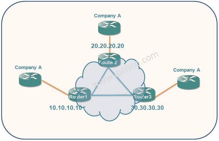
Table of Contents
In this VPLS Example, we will focus on the VPLS (Virtual Private LAN Service) Configuration on Cisco Catalyst 6500 Series Switches. We will use the below Cisco VPLS (Virtual Private LAN Service) topology for our VPLS Configuration Example.

In this Cisco VPLS Example topology, we will use Cisco Catalyst 6500 Series Switches. Here, before the configuration, lets check two terms used in commands. These are:
Here, For our VPLS Configuration, we will follow the below configuration steps:
We will do these configuration steps one by one for each PE device.
There is an important note before VPLS Configuration. As you know split-horizon rule provides broadcast packet loops and isolates the L2 traffic. With the use of “no-split-horizon” command during the VC configuration, we can disable the default L2 split-horizon rule and configure multiple VCs per spoke into the same VFI. As an example:
Router1(config-vfi)# neighbor 20.20.20.20 encapsulation mpls split-horizon
Let’s see the VPLS (Virtual Private LAN Service) Configuration on each device.
Firstly, we will enables Layer 2 VFI manual configuration mode with “l2 vfi vfi-name manual” command. Here, our vfi-name is PE1_COMPANY_A.
Next, we will use “vpn id vpn-id” command to configure VPN ID for a VPLS domain. Our VPN ID is 100.
Then, we will use “neighbor router-id {encapsulation mpls}” command. With this command we will set remote peer router ID and the tunnel encapsulation type or the pseudo-wire property to be used to set up the emulated VC. We have 20.20.20.20 and 30.30.30.30 neighbors.
Router1(config)# l2 vfi PE1_COMPANY_A manual
Router1(config-vfi)# vpn id 100Router1(config-vfi)# neighbor 20.20.20.20 encapsulation mplsRouter1(config-vfi)# neighbor 30.30.30.30 encapsulation mplsRouter1(config-vfi)# exit
After that, we will configure 802.1Q Access Ports for Untagged Traffic. Under the interface, with “switchport” command we will modify the switching characteristics of the Layer 2-switched interface. With “switchport mode dot1qtunnel“, we will sets the switch port encapsulation format to 802.1Q. With “switchport access vlan 100” we will sets VLAN 100.
Router1(config)# interface FastEthernet0/0Router1(config-if)# switchportRouter1(config-if)# switchport mode dot1qtunnelRouter1(config-if)# switchport access vlan 100Router1(config-if)# exit
Here we will creates a switched virtual interface (SVI) and then we will disables IP processing on this interface. Then we will specify layer 2 VFI that we will bind to the VLAN port with “xconnect vfi vfi-name” command. Here, our vfi-name is PE1_COMPANY_A.
Router1(config)# interface vlan 100Router1(config-if)# no ip address
Router1(config-if)# xconnect vfi PE1_COMPANY_A
We will configure Router 2 and Router 3 similar to Router 1 with different variables. Below, you can find both of these routers’ configurations.
Router2(config)# l2 vfi PE2_COMPANY_A manual
Router2(config-vfi)# vpn id 100Router2(config-vfi)# neighbor 10.10.10.10 encapsulation mplsRouter2(config-vfi)# neighbor 30.30.30.30 encapsulation mplsRouter2(config-vfi)# exitRouter2(config)# interface FastEthernet0/0Router2(config-if)# switchportRouter2(config-if)# switchport mode dot1qtunnelRouter2(config-if)# switchport access vlan 100Router2(config-if)# exitRouter2(config)# interface vlan 100Router2(config-if)# no ip address
Router2(config-if)# xconnect vfi PE2_COMPANY_A
Router3(config)# l2 vfi PE3_COMPANY_A manual
Router3(config-vfi)# vpn id 100Router3(config-vfi)# neighbor 10.10.10.10 encapsulation mplsRouter3(config-vfi)# neighbor 20.20.20.20 encapsulation mplsRouter3(config-vfi)# exitRouter3(config)# interface FastEthernet0/0Router3(config-if)# switchportRouter3(config-if)# switchport mode dot1qtunnelRouter3(config-if)# switchport access vlan 100Router3(config-if)# exitRouter3(config)# interface vlan 100Router3(config-if)# no ip address
Router3(config-if)# xconnect vfi PE3_COMPANY_A
To verify our VPLS Example, we will use the below verification commands.
Router1# show mpls l2 vc
Router1# show vfi PE1_COMPANY_A
Router1# show mpls l2 vc det
In this VPLS example, we have used a simple VPLS (Virtual Private LAN Service) topology and we have configured Cisco VPLS on Cisco Catalyst 6500 Series Switches.


Why I cannot see the full content?
Hi Monir, you account is Active.
do you have an access problem?
Kindly send an email to info@ipcisco.com about it.