- COURSES
- SPECIALS
- BLOG
- MEMBERS
- SHOP
- ABOUT
- ENROLL HERE

Table of Contents
NTP is the aberviation of Network Time Protocol used to set time related configurations on network devices. In Cisco devices, NTP Configuration is done with a little various NTP commands. In this example, we will see how to configure NTP on Cisco devices. You can also check Cisco PTP Configuration Example.
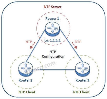
Here, we will use the below simple network topology. We will configure the network devices as NTP Server and NTP Clients. Router 1 will be our NTP Server. Router 2 and Router 3 will be our NTP Clients. For this example, think about that Router 1 gets time information from pool.ntp.org. This means that the origin of time information will be pool.ntp.org. The NTP server router will be periodically updated from this website.
Let’s start and see how can we synronize our network’s time with Cisco NTP Configuration. But before doing the configuration with a real time source, let’s also learn how to configure time on NTP Server manually.
Firstly, we will configure router time manully. timezone. Here, think about that you are in Washington DC. Washington is in the Eastern Standard Time Zone -5 (EST-5).
Router 1(config)# clock timezone EST -5
By the way, here, “-5” means that our location is 5 hours behind Universal Time Coordinated (UTC).
After that, we will configure the day light saving settings. In some countries you enable this and in others you do not. This is according to the country that the devices resides in. For this configuration, we will configure day light saving settings.
Router 1(config)# clock summer-time EDT recurring
Here, the “recurring” keyword means that the time will be forwarded at spring and will be taken back at fall.
In this step, we will set the exact time on our device. Here as our date and time, we wil set “09:35:00 29 May 2022”.
Router 1(config)# clock set 09:35:00 29 May 2022
Router 1(config)# exit
These are manual steps of time configuration on an NTP Server. But if we have a real time source, then we can use it instead of setting the time manually. Below, we will shwo how to set it on NTP Server. But before server configuration, let’s configure NTP Client.
To set a Cisco device in the network as NTP Client, we set NTP Server Address on it. With this command, we say that, this device is NTP Client and its NTP Server is another device.
Here, our NTP Client devices are Router 2 and Router 3. So, we will configure NTP Server address on these devices. Here, as NTP Server address we will use the Loopback Address 0 of Router 1. This is also a best practice for high availability.
We can also use “ntp peer ip-address” command here. With this command we set two devices as NTP peer. This command provides time syncronisation between these two devices. Here, interface ip address of Router 2 is 10.10.10.2/24 and Router 3 is 10.10.10.3/24.
Router 2# configure terminal
Router 2 (config)# ntp server 1.1.1.1
Router 2 (config)# ntp peer 10.10.10.3
Router 3# configure terminal
Router 3 (config)# ntp server 1.1.1.1
Router 2 (config)# ntp peer 10.10.10.2
In NTP Configuration, to set a Cisco device as NTP Server, we use “ntp master stratum-level” command on it. The stratum level is the reliability of the NTP Server. Stratum-level 1 is used for public NTP Servers. Here we will set one router as NTP Server, so, we will use stratum level 2. Here, the clients will be stratum level 3. As we have mentined above, our NTP server will get the time from a source, from pool.ntp.org. The stratum level of this original source is 1.
Here, there is one more important command. This is “ntp update-calender” command. With this command, hardware clock of the server router is updated by the original clock source.
Router 1# configure terminal
Router 1(config)# ntp server pool.ntp.org
Router 1(config)# ntp update-calender
Router 1(config)# ntp master 2
To verify our time, we will use “show clock” command.
Router 1# show clock

09:35:00.145 EDT Wed May 29 2022
Router 1# show clock details
09:35:00.145 EDT Wed May 29 2022
Time source is user configuration
As you can see above, with “show clock details” command we can see also the first configuration type of the time. Here, in NTP Server, it is “user configuration”.
Below, in NTP Clients, the output of “show clock details” command shows that the clock set is done via NTP.
Router 2# show clock details
09:35:00.145 EDT Wed May 29 2022
Time source is NTP
Router 3# show clock details

09:35:00.145 EDT Wed May 29 2022
Time source is NTP
To verify NTP Configuration, we can also use “show ntp status” and “show ntp associations” commands.
Router 2# show ntp status

Clock is synchronized, stratum 1, reference is 1.1.1.1
nominal freq is 200.0000 Hz, actual freq is 200.0000 Hz,
ntp uptime is 1003200 (1/100 of seconds), resolution is 5400
reference time is D6744147.125DEA4 (09:35:00.145 EDT Wed May 29 2022)
clock offset is 0.0523 msec, root delay is 1.99 msec
root dispersion is 29.34 msec, peer dispersion is 4.21 msec
loopfilter state is 'CTRL' (Normal Controlled Loop), drift is 0.000000005 s/s
system poll interval is 64, last update was 120 sec ago.
Router 3# show ntp associations

! This output is taken from router Router 3, acting in client mode
  address         	ref clock       	st   when   poll reach  delay  offset   disp
*~1.1.1.1	10.10.10.10 	75     64   452  1.220  -5.845  2.158
Leave a Reply