- COURSES
- SPECIALS
- BLOG
- MEMBERS
- SHOP
- ABOUT
- ENROLL HERE
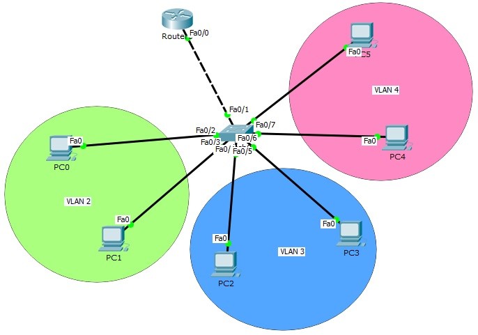
Table of Contents
VLANs are the virtual LANS that provide divide your big network, into smaller pieces. Many companies use to divide their networks into different departments. We have discussed the basic logic of VLANs in the previous articles.As you know each VLAN is a seperate VLAN. Each of them is a single network. So at the beginning, there is no communication between VLAN. To enable the communication of these different sub networks, we need Inter VLAN Routing. In other words, this topology called “Router on Stick” topology. Inter VLAN Routing topology or Router on Stick topology is a very common topology for CCNA exams. We will learn Routing on Stick Topology and Router on Stick Config on this lesson.
You can DOWNLOAD the Packet Tracer example with .pkt format At the End of This Lesson.
You can also DOWNLOAD all the Packet Tracer examples with .pkt format in Packet Tracer Labs section.
You can download “Cisco Packet Tracer” in Tools section.
You can Check Full Cisco Hands on Course With Packet Tracer
In this article, we will use the below Router on Stick topology and we will configure Inter VLAN Routing on Packet Tracer.

For Router on Stick topology (Inter VLAN Routing) configuration, we will create router virtual interfaces under the router interfaces. Then, we will assign each of this virtual interface to a specific VLAN. We will also create our VLANs and configure the PCs on that VLAN. For Router on Stick topology (Inter VLAN Routing), we will use one switch, one router and six PCs in Packet Tracer. And we will have 3 VLANs.
Let’s start to configure our Router on Stick topology (Inter VLAN Routing).
We will use 10.0.0.0/24, 20.0.0.0/24 and 30.0.0.0/24 blocks for our Packet Tracer Router on Stick topology example. The first block will be for VLAN 2, the second will be for VLAN 3 and the last one will be for VLAN 4.
Firstly, we ll configure the IP addresses of the PCs on Packet Tracer like below.
PC0 : 10.0.0.2 255.255.255.0
GW : 10.0.0.1
PC1 : 10.0.0.3 255.255.255.0
GW : 10.0.0.1
PC2 : 20.0.0.2 255.255.255.0
GW : 20.0.0.1
PC3 : 20.0.0.3 255.255.255.0
GW : 20.0.0.1
PC4 : 30.0.0.2 255.255.255.0
GW : 30.0.0.1
PC5 : 30.0.0.3 255.255.255.0
GW : 30.0.0.1
Here, the gateway addresses of the PCs will be the IP address of router virtual interfaces. Each router virtual interface will have an IP addresses as gateway of one of the VLANs.
Now, let’s configure our VLANs and assign the interfaces to these VLANs. Firstly we will create VLAN 2,3 and 4. Then, we will enter the interface range and configure the interface range as access interface. Lastly, we will assign the interface to a specific VLAN with “switchport access vlan” command.
Switch (config) # vlan 2
Switch (config-vlan) # vlan 3
Switch (config-vlan) # vlan 4
Switch (config-vlan) # exit
Switch (config) # interface range fastEthernet 0/2-3
Switch (config-if-range) # switchport mode access
Switch (config-if-range) # switchport access vlan 2
Switch (config-if-range) # exit
Switch (config) # interface range fastEthernet 0/4-5
Switch (config-if-range) # switchport mode access
Switch (config-if-range) # switchport access vlan 3
Switch (config-if-range) # exit
Switch (config) # interface range fastEthernet 0/6-7
Switch (config-if-range) # switchport mode access
Switch (config-if-range) # switchport access vlan 4
Switch (config-if-range) # exit
Our VLAN configurations are OK on the switch now. Let’s verify the VLANs.
You can also DOWNLOAD all the Packet Tracer examples with .pkt format in Packet Tracer Labs section.
Switch# show vlan

VLAN Name Status Ports
---- -------------------------------- --------- -------------------------------
1 default active Fa0/8, Fa0/9, Fa0/10, Fa0/11
Fa0/12, Fa0/13, Fa0/14, Fa0/15
Fa0/16, Fa0/17, Fa0/18, Fa0/19
Fa0/20, Fa0/21, Fa0/22, Fa0/23
Fa0/24, Gig0/1, Gig0/2
2 VLAN0002 active Fa0/2, Fa0/3
3 VLAN0003 active Fa0/4, Fa0/5
4 VLAN0004 active Fa0/6, Fa0/7
1002 fddi-default act/unsup
1003 token-ring-default act/unsup
1004 fddinet-default act/unsup
1005 trnet-default act/unsup

AN Type SAID MTU Parent RingNo BridgeNo Stp BrdgMode Trans1 Trans2
---- ----- ---------- ----- ------ ------ -------- ---- -------- ------ ------
1 enet 100001 1500 - - - - - 0 0
2 enet 100002 1500 - - - - - 0 0
3 enet 100003 1500 - - - - - 0 0
4 enet 100004 1500 - - - - - 0 0
As you can see, for our Router on Stick topology, Interface Fa0/2 and Fa0/3 are the member of VLAN 2, Interface Fa0/4 and Fa0/5 are the member of VLAN 3, Interface Fa0/6 and Fa0/7 are the member of VLAN 4. Interface Fa0/1 is not on the VLAN table. Because it is our Trunking port.
It is time to configure the switch’s router face interface, interface 0/1. We will connect switch to the router, with this interface. This interface will be a trunk port. In our Router on Stick topology, Trunk interface will pass all our VLANs that we allowed.
Switch (config) # interface fastEthernet 0/1
Switch (config-if) # switchport mode trunk
Switch (config-if) # switchport trunk allowed vlan 2,3,4
Switch (config-if) # exit
Our switch configuration is ok, on Packet Tracer. We can configure the router, Router on Stick now. On Router on Stick, we will configure Fa0/0 interface and the router virtual interfaces under this interface for Inter VLAN Routing.
Router (config) # interface fastEthernet 0/0
Router (config-if) # no shutdown
Router (config-if) # exit
You can Check Full Cisco Hands on Course With Packet Tracer


I found this website very full of stuff and help full for network Job seeker or Job holders
Thank you very much Asif;) You are alwasy welcome to IPCisco.com!